Woodworking/Shop

DIY Cornhole Game Set

DIY Cornhole Game Set

For a luau-themed software launch party at meltmedia, we wanted to be able to play Cornhole. I don't know that Cornhole is a regular game played at traditional luaus, but at meltmedia luaus it is. As I am the Chief Tinkerer (see proof on Instagram) at meltmedia, I volunteered to build the game parts for the festivities. If you're not familiar with Cornhole, it's a very simple game: Toss little corn-feed-filled cloth bags at a 6" hole in 24" x 48" board that's about 30' away from you. For all the official rules, go to (I'm not kidding, here) the Official Cornhole Rules page at the American Cornhole Association website. It's hard not to giggle.

If you have even the most basic of woodworking skills and tools, you can do this.

Foam Core Backdrop Support Frame

Foam Core Backdrop Support Frame

At the meltmedia office we're making a video podcast once a week. Our design team made a cool backdrop for the little studio area we use. It's a big-ass inkjet direct-print on a full 8' by 4' sheet of foam core. As you can guess, it was a bit floppy and needed some kind of support behind it.  It also needed to be lightweight because we wanted to be able to hang it on the whiteboard behind us so we could easily remove it and replace it when we needed the whiteboard. I looked around the garage and all I had that was long enough was an 8' 2x4. So, the entire frame is made from that single pine 2x4. I ripped three 1" strips from it. to get the top, bottom and sides. The sides are just a long piece cut in half.


Introducing: The Office Chairiot Mark II - Labor In Motion Again

Introducing: The Office Chairiot Mark II - Labor In Motion Again

What is electric, goes somewhere between 15 and 20 miles per hour and has an Ikea chair on it?

The Office Chairiot Mark II is the second generation of motorized office chair brought to you by yours truly. Why motorize an office chair? That's a silly question and I will not dignify it with an answer. Office chairs are boring. Plus, on a hot summer day, I walk too slowly between our office buildings in ARIZONA. The Office Chairiot Mark II can do it in a fraction of the time and I sweat far less driving it.

Electronics and Hack Workbench

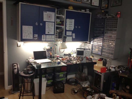
I've had a number of requests from readers to see my workbench in its entirety, as most photos of it are just backgrounds to projects. So, I thought I'd post some photos and explanations in an article. Maybe someone will get some helpful hints or perhaps someone will lend me some helpful advice. First off, here are some wide shots of the mess:

Wide shot of Andy's Electronics Workbench

I made the table. The top is made out of three 10"-ish wide pine boards glued together side to side using biscuits. I had a custom piece of 3/16" glass to fit the top. Half of the top of the table is covered with conductive foam to keep static at bay. I ordered a couple big pieces of that from somewhere on-line, can't remember where. It's super convenient for stabbing parts into to hold them neatly. It's also great for discharging static. The legs I've had a while. They were part of a giant desk I built years ago. I got them on-line many moons ago. They have bases that are screwed to the bottom of the tabletop. They then screw into the bases. They're made of steel or aluminum or something strong like that. Under the tabletop, I put a big "X" of 3" wide interlocked pine planks for rigidity. I can stand right on the center of that table and it barely flexes.

Thrown together cubby shelf thing

Down below the desktop is a six-cubbyhole shelf on little rubber footies leftover from my table saw stand (that is now attached to a rolling platform I made). In each of those cubbies, I put plastic lock-top containers full of various larger items, like wall warts, scavenged PCBs from VCS and such, and cords. This is a great use of space that would otherwise be cluttered up with piles of things.

The blue cabinets came with the house. As with most of the light fixtures and some other miscellaneous pieces left behind by the previous owners, I'm guessing they're from Ikea. They're really handy. I added the little white shelves between the two cabinets. I have a benchtop digital power supply on the lowest shelf for easy access, but that's not my main power source. I'll get to that shortly.

Shelves between Ikea cabinets

I taped up a bunch of my most-referenced cheatsheets for things like pinouts on ATmega328's, ATtiny13's, common capacitor markings, resistor bands, ISP cables, etc. I also keep my DMM hanging right there and made a little wire hook for the leads.

Parts drawers are SUPER handy!

The parts drawer cabinets on the right of the bench are typical types from Home Depot or Lowes. The more the merrier, as you can see. I keep groups of similar things close together. Eventually, there will be more of these. However, I have to get more creative with my space. To the right of the cabinets is a big painting that I commissioned for my Man Cave™ that I'd prefer not to move.

In some of the larger drawers, I use the conductive foam to hold my many ICs in layers to save space and for organization. I label each group with my handy Brother P-Touch labeler, like so:

Stacking ICs in drawer with conductive foam and labels

Here's another angle on how I stack the ICs in the larger drawers:

Logic ICs stacked on ESD foam, labeled for a quick find

I then put an index label on the front of the drawers so I can easily find families of ICs. I haven't yet found a really cool method for storing the 8 zillion resistors I have, but I do sort them by sub-1,000Ω, 1KΩm and 1MΩ drawers. Miscellaneous electrolytic caps are in one big drawer, common caps that are still in their tape from the manufacturer are generally sorted into smaller drawers.

I label the fronts of the drawers sometimes, especially when the drawer is clearly something that will always contain what it currently contains. In the case of my stacks of DIPs and whatnot, they very well organized.

Parts drawers with Sharpie-scribed labels

I have so many parts, now, that I have built a spreadsheet to track them. A majority of the parts I have I've thrown on the end of orders because the parts looked cool or handy. When a grab bag of common transistors will only add a couple of dollars to an order, why not? AVRs are my favorite microcontroller, so I have a drawer dedicated to various renditions of that family of chip, as you can see on the middle left drawer above.

MacBook Pro sans battery as benchtop computer

I don't know if people notice this in the background or in screenshots, but I use a 15" MacBook Pro for my benchtop computer. The battery failed, so it's always plugged into AC, now. It's now a flip-open desktop workstation, pretty much. I use this MacBook Pro to program microcontrollers and to have convenient access to the web and what not.

Our house is all Mac all the time. I have a Dell box used as a network storage server, but that's it. My regular desktop is a big-arse 27" 3.4 GHz iMac with a second 27" Cinema Display. Both are on wall-mount arms which are supposed to make my desk cleaner. However, as you can see in the photo below, all that's done is make more room for me to pile parts.

3.4 GHz iMac 27" with matching 27" Cinema Display over desk

Of course, what desk area would be complete with a jackalope and an oil painting of a monkey in a fez?

Repurposed Dell PC power supply as benchtop power supply

About my primary power supply... I took apart a my wife's old computer that she had when we met. It was a sad, sad old computer I'd given her to get her by that I think I salvaged from my uncle's office. The power supply makes for a fantastic DC power supply. It provides very clean and reliable 3.3VDC/14A, 5VDC/22A, and 12VDC/10A power. This was crucial when I was working with peltier devices, which drew more amperage at their ideal voltages than the digital power supply could give them. This Dell power supply doesn't even break a sweat when a peltier device asks for 3.5A. The max on my digital PS is only a little shy of 3A.

Temporary switch for Dell power supply

I turn the supply on or off using this little toggle switch I rigged into the main jumper for the power supply.When I become ambitious about really finishing organizing my bench, I will snip all the extra wires and connectors and clean up the power supply. I'm also going to extend the voltage and ground leads and put nice ends on them to make it easier to connect and disconnect them from my many breadboards. Speaking of...

Custom breadboard power supply adapter

I whipped together this little adapter so that I could quickly connect and disconnect the various voltage leads from the power supply to my breadboards. I quickly got tired of screwing and unscrewing the thumbscrews on the breadboards when I wanted to switch them out. Eventually, these connectors will be on-the-ready toward the back of the benchtop and the switch for the power supply will be mounted more conveniently. The power supply will be relocated up and out of the way. Right now, sadly, it sits on two pieces of wood on the ESD foam.

When I work with my favorite microcontrollers, the AVR series from Atmel, I don't usually use a proper Arduino board, even though I tend to use the Arduino IDE. Instead, I whip together a quick circuit with either a 16 MHz or 20 MHz quartz crystal on a breadboard. I usually have three or so of these setup and ready to tinker with. I do actually have a few different types of Arduinos I've purchased with gift cards, recently. Here's an example of a typical setup for me:

Quick AVR setup with supporting circuit on breadboard

I followed the recommendations from the ATmega328 datasheet for what components to put around it. There's a 10µH inductor on the analog voltage reference pin (in the photo above, it's on the Vcc pin, so ignore that). There's a 20 MHz quartz crystal on the XTAL1 and XTAL2 pins. Each of those pins is also connected to ground with 20 pF capacitors. Often times, I put a 7805 5V linear regulator on the + rails of ones side of the board and the other has either a 7812 12V regulator or LM10863V3 3.3V regulator on it. Of course, the proper capacitors near the regulators to clean up power are usually on there, as well. Don't forget the polarity diode so that you don't accidentally hook up the power supply leads backwards and cook something or popcorn an electrolytic capacitor.

As you can see from some of the above pictures and the one below, the edge closer to where I work on the glass surface gets cluttered with the parts I reuse the most.

Parts clutter on my ESD foam

About once every few months, I will clean up the area and put things back where they belong.

Field Notes® brand notebooks for diagrams and doodles

I keep my notes and diagrams and doodles in these awesome little Field Notes® brand notebooks with graph paper inside. They're about $10 for a 3-pack and each notebook has 48 pages in it. They're the perfect size to sit on the bench next to a project. Not so big that they require a lot of open space. Not so small that they're just not useful.

Last, but not least, I present my bourbon cabinet, complete with my hand-dipped (by me at the distillery) Maker's Mark® bottles. I have in my collection about 20 different bourbons. My goto at when we're out and about, of course, is Maker's Mark®. :)

That's it for the tour. If any of you have suggestions or comments, please, please leave them below in the comments section. I'd especially love to hear how you guys are storing your resistors. The ultimate trick still eludes me. I don't want to waste a little drawer for a single value, of course. Dividing up the drawers makes it too time-consuming to get one. I'm thinking along the lines of a Rol-O-Dex of resistors or something. I dunno. Comment away.

Desktop Warp Core - The SMD LED Strip Years

I threw together a video of the warp core's control circuit and eight stupidly bright white SMD LED strips for the rings. The original rings were going to be through-hole bright LEDs, but I realized how much soldering and drilling would be required for that. That is dumb and painful. So, factory-built strips of LEDs, complete with self-adhesive backing, resistors, and snap-on wire ends ready for 12-volt DC power it is! Here it is in action:

There will be more to come as we start to construct the body of the warp core.

Domo Wobbly Balancing Robot Thing

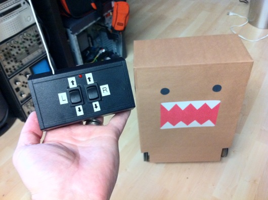
Completed Domo Wobbly Bot and Remote The Short Attention Span version: I ripped apart a cheap remote controlled car and repurposed most of the parts into a self-balancing robot based on the Domo character because I thought one of the partners of the company I work for would enjoy it, as he seems to enjoy Domo stuff. I got the idea from a coworker who suggested I build this for the Domo partner.

The idea is not original to me. I was sent a link to Instructables.com that showed one in action. I didn't follow the directions, so the engineering is my own brew. But, I will say, that's an ingenius way to make an upright, two-wheeled roboto-doo-dad.

Here is the YouTube video of the robot in action:

So, the first thing I did was destory this car (or it was a close cousin):

Viper RC car

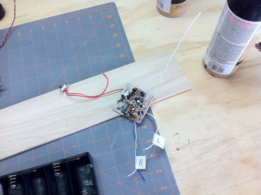
I took out the main circuit board from the car and the circuit board from the remote.

RC car circuit board

I figured out which wires ran which motor. One set ran the drive motor to make the car go zoom. The other set ran a motor that simply turned the steering all the way to the left or all the way to the right. No in-between steering on this one. The front wheels self-centered thanks to a little spring. BUT, we had two motors controllable by two rocker buttons on a remote and that's all we needed.

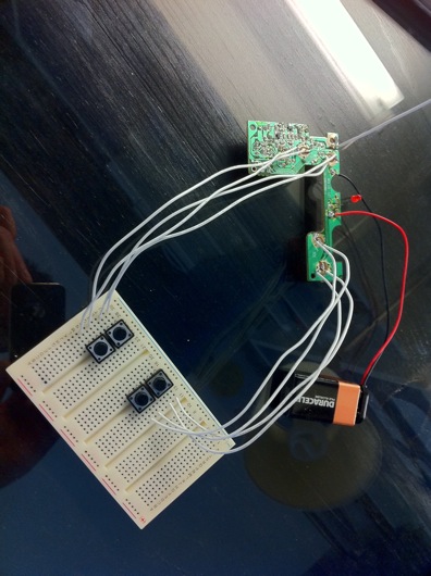
RC car remote control circuit board

I ordered some little rocker switches, a battery, and a plastic project box into which I could mount the remote stuff. I wound up trimming the circuit board down and resoldering the leads to the buttons so that it would fit snuggly in the project box.

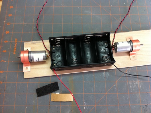
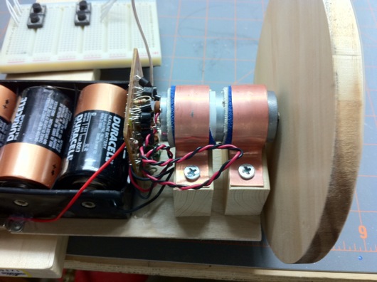
4 D-cell battery holder and geared motors

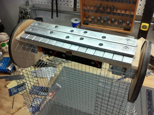
I made the base and wheels (shown later on) out of some poplar I had lying around. I guesstimated all the sizes and dimensions, basing them around the way things kinda fit together on the board I used for the base. I ordered some geared down DC motors from AllElectronics.com. The wheels needed to not spin too quickly or Domo would constantly slam his head down on the ground. Gearing down the 6V supplied by the circuit was simple and cheap.

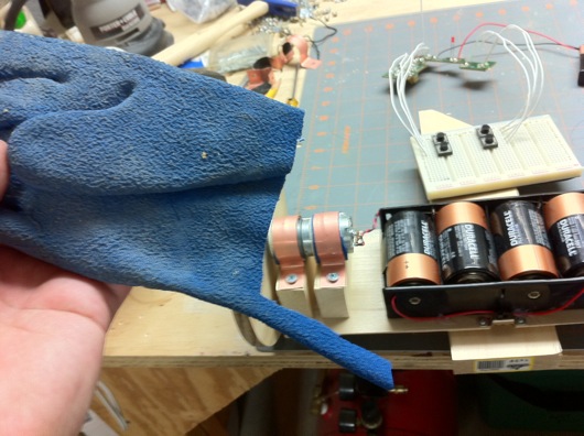
Rubber glove for grippy goodness

I cut strips of rubber gloves and lined the copper motor brackets with them. This did a nice job of preventing the motors from twisting themselves when starting up. At the point I built the base of the bot, I hadn't purchased the bike inner tube that I used to cover the wheels to make them more grippy-tactic, otherwise I would have used that material.

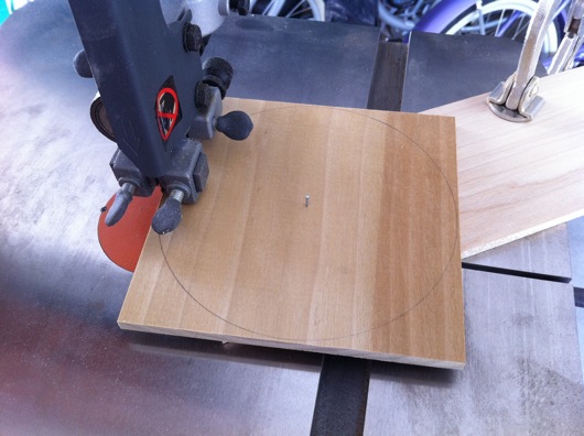
Perfect circle wheel bandsaw jig

Next, I needed to make wheels that were as circular as I could get them so that Domo didn't roll with a limp. I searched the web for easy jigs to cut circles with bandsaws. The crazy-simplest one I found was just a brad nail in the dead center of the circle to cut and a board below on which the piece being cut could rotate. Place an edge of the circle up against the blade and SLOWLY start rotating the piece. I say SLOWLY because pushing too quickly makes the blade run off-course. I have new round scraps of wood to prove it.

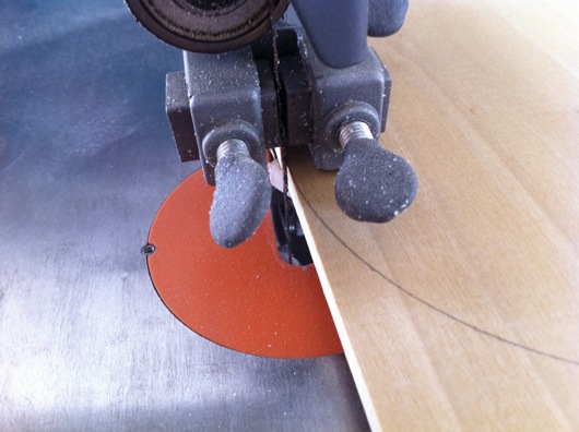
Bandsaw blade against circle to cut

Notice the lower piece right behind the blade. The closer that bottom piece is to the blade, the better it supports the piece being cut. The cut needs to start at the edge of the circle because we're only going to rotate the piece being cut. If you don't scribe your circle as perfectly as you can and you don't put that rotation point as dead-center as possible, it won't be a beautiful circle when it's completed.

Close-up of wheel and motor mounts

At first, I only used a single motor bracket. That gave the robot a sloppy angle on the wheels, so I added a second bracket to help sturdy up the axles. The wheels were 1/4-inch at first. I switched those out with 1/2-inch to add a little more stability to the wheels. As you can see in this photo, I simply hot-glued the main board in between the batteries and the right side motor.

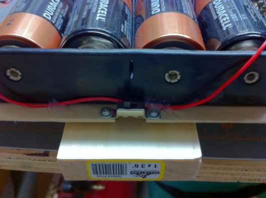
Power switch mounted in the butt

I cut a notch and mounted the power switch facing downward, initially. That was painful and dumb. So I flipped it over. Why? First time the bot made a turning start, he switched himself off. Duh.

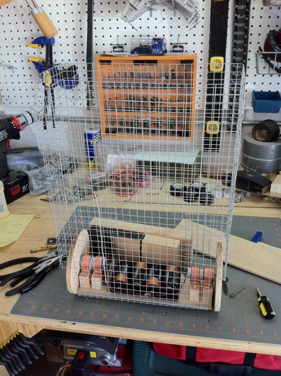
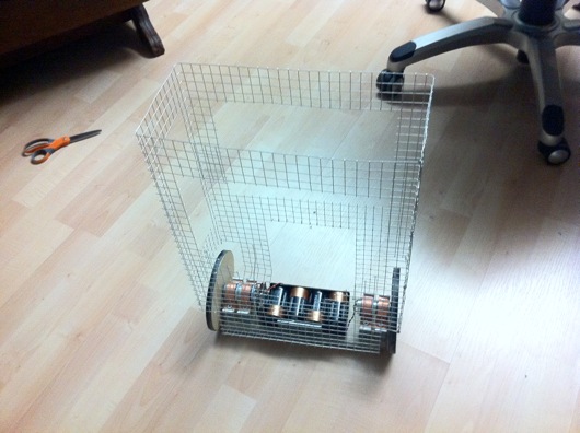
Skeleton made from garden mesh wire

Now, as mentioned above, the whole idea behind this thing staying upright on its own is for it to have a heavy butt. With four D-cells and a bunch of metal bars and wheel balancing weights, you'd think that would be enough to counter that wire frame. You'd be wrong about that. I had to snip out a bunch of that wire to lighten the load to make him more bottom-heavy.

Wire poked through bottom and ground down

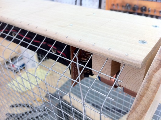
To firmly attach the skeleton to the butt, I left plenty of extra pokey wires on the bottom edge of the skeleton. I then drilled holes in the base and pulled the skeleton down through them. I bent the wires outward and then ground them down. In fact, EVERY STEEL wire sticking out needed to be ground down. I know have lots of little holes in my hands and arms, thanks to that incredibly pointy steel wire.

I bent the shape of the skeleton on my table saw. I used a metal straight edge to push each bend down into the miter slots on the steel table of the saw. It worked great! Since I always do my own stunts, climbing up on the table saw wasn't that big of a deal.

Plenty of weight in the butt

For the bot to stay upright, as mentioned above, weight was key. Besides the big batteries, I needed some more weight below, so I picked up some joist repair bars at Home Depot. They're heavy and they have nice countersunk screw holes in them. I mounted four of them to the base and then used some car wheel balancing 0.5 gram weights I got free from a very nice guy at Pep Boys Auto Parts. I used the little weights to get the bot balanced and vertically straight. It's incredibly heavy, but stable.

Skeleton after weight reduction surgery

Another thing I think I mentioned before was the need to lose some weight up top. I cut some strategic holes into the body to lighten the load. It worked perfectly.

Construction paper is fun

With the help of a little construction paper and a glue stick, the body is complete. At this point, as you can see in the photo, the body construction paper isn't bent inward down near the base. I eventually did that and tacked the edges every inch or so with some hot glue for good measure. I also put construction paper on the wheels to add some nice finish to the thing.

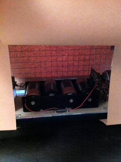
Butt battery and power access flap

The power switch and the batteries are accessible through a flap in Domo's butt. It sometimes flaps in the breeze while he's running around, like the tails of a tuxedo coat.

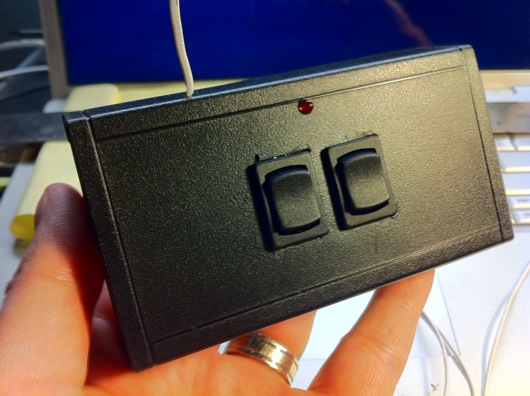
Domo remote in project box with rocker switches

I got a handful of slick little rocker switches to run each motor forward or backward. I did some minor butchering on the holes underneath the flanges of the switches. What does one expect for a free robot skinned in construction paper? The red LED is the original from the RC car remote. The antenna was a piece of wire I had on my bench. To change the 9-volt battery, you just unscrew the four screws on the bottom of the box. Easy.

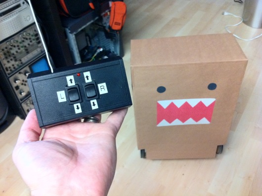
Controller and Domo bot

I used my trusty little label maker and put some stickers on the buttons to aid in its use.

To steer Domo around, you drive him like a tank: Push both buttons forward to move forward in a straight line. Push just one to make a wider turn. Push both buttons opposite each other to spin him in place. Push both buttons back and he goes straight back.

Dave, the guy I gave the bot to, has a dog. The dog doesn't like the bot. It is funny to watch, though.

12VAC Power Supply from Ikea Wall Wart Light Power Supply

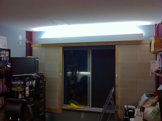
I recently rebuilt the lighting in my office because the crappy 12-volt strung lighting from Ikea that the previous owner installed was insufficient for working comfortably in my Man Cave™. Here's the NEW lighting above the sound-proffed barn door window shade things: New Man Cave™ Lighting

With the intensity of the photo cranked down a bit, you can see the simple valence I made out of pre-primered pine trim board:

Valence around new Man Cave™ lighting

The old lighting was 12VAC wire cable lighting with halogen lights. You seem the at Ikea. Two steel cable strung between two walls and the halogen lights hang between the wires at regular intervals. It's really cool, but it isn't very bright and the light is very yellow. I like daylight-ish fluorescent lighting, so that's what I bought to replace the old stuff.

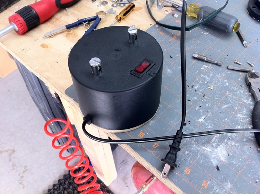
Now, on to the real story: I salvaged the wall wart transformer/power supply for the 12VAC lighting and made a simple 12VAC power supply out of it. Not sure what I'll use that for, yet, but it was fun and I feel like I saved the landfill from containing weird metal and plastic parts.

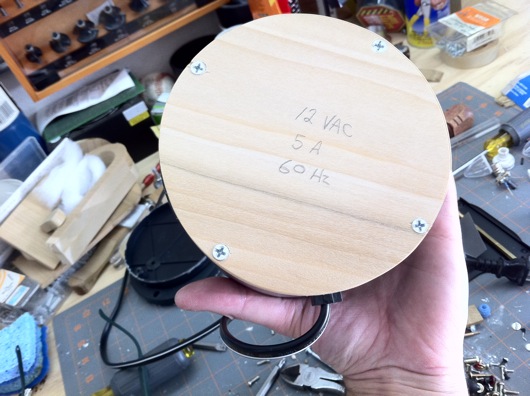
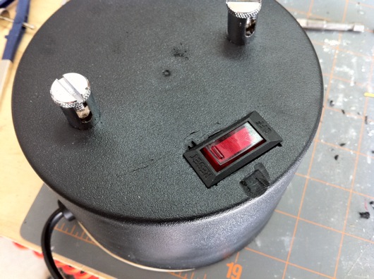
I removed the pushbutton fuse reset thing and replaced it with a neon lamp power switch with a fuse reset feature and then cut a notch in the base of it to hold a strain-relief thing for a power cable from an old VCR I torn down. Then I put a wood base on the back and screwed in to together and sanded it for a nice finish. I haven't painted the edges black, yet. I also need to put little rubber footies on it to keep it from sliding around on the glass top of my electronics workbench.

Here are the photos:

12VAC transformer power supply

Completed power supply with power cord and switch.

Poplar Wood Bottom

Bottom is screwed into four holes built into case of wall wart. I wrote the specifications from the sticker on the transformer inside so that I would not forget how this could catch fire or trip a fuse.

Fuse reset button replaced with on/off/reset switch

I realized after I put it all together and tested the power that the replacement power switch might not trip at the same power draw as the old pushbutton. So, when I laid a big piece of copper wire across the terminals, it sparked and never did trip the switch OR the circuit breaker for the garage workbench. That's probably a fire hazard, but I'll usually have a good quality surge strip (or two) AND a house circuit breaker between my mishaps and the neighborhood power lines.

Tony Stark for Halloween 2010: The Arc Reactor (RT Mark II)

UPDATE: Want a PCB and components for your own project? I've had a deluge of requests for the PCBs for this project. If you're interested, please contact me through this blog. I'm trying to figure out whether it's worth it to sell the boards alone or maybe as a kit with the LEDs and resistors (or current limiting devices) or maybe even assembled (LEDs, resistors and power leads). I have been dying to post photos of my latest colossal time-sucker-of-a-project: My Halloween 2010 costume is Tony Stark. Iron Man would have been a pain in the mechanical arse, but Tony Stark's only challenge is that crazy super-glowy round life-saving thingy thing in his chest which is visible under a shirt. This is the most ridiculous and complicated build I've done to date.

This post is about building the arc reactor Tony Stark needed to survive in the Iron Man movies. The particular version I wanted to build was the RT Mark II, which Tony built in his home lab once he got home from his captivity in the desert. It's more refined than the first version he built in the cave and every bit as swanky. Mostly, I liked the look of the second one better, myself. The one I'm talking about can be seen in the movie fairly up-close when Pepper Potts has to remove the old one and replace it with this new one.

So, first thing's first... I had to create a round circuit board (and a circuit, for that matter) with some super-bright LEDs that wouldn't catch fire under my shirt and, at the same time, would be visible from space from under my shirt. Ideally, I wanted this thing to stay fairly bright for as long as possible, like, say, a long night at a Halloween party. I'm just sayin'... I shopped around at SuperBrightLEDs.com and found some 5mm square surface-mount LEDs. These little doods have THREE little ultra-bright LEDs in each little 5 mm X 5 mm X 1.5-ish mm package. The blue ones that I used in the were so bright that when properly powered, they left greenish-yellowish spots in my vision for a while after looking at them.

I wanted the PCB to be functional, of course. It needed to properly connect the parts of the circuit together. But, I also wanted the traces to look movie-like. Busy, complex, important, and artsy at the same time. I design the circuit in Illustrator and tried my best to make the traces look like they were more than just power for LEDs:

Circuit board plans

You can see that the PCB design even includes the Stark Industries logo at the top. The zig-zaggy parts are the landing pads for the SMD LED packages. They have three anodes on one side and three cathodes on the other. I ran each SMD LED package's individual LEDs in series. There are 14 total SMDs, or 14 total three-LED series circuits. Each of the 14 series LED circuits connects to the ground bus (the outer ring in this design) and +9.6 volts via the center "C" ring. The little squares are the through-holes for the 15-ohm resistors for each of the 14 SMDs. The final etched board looks like this:

Finished etched printed circuit board

The fuzzy edges and weird texture on the traces are due to some craptastic refurb toner cartridges I bought for our HP 2600n color laser printer. The black cartridge deposits a funky pattern of toner all over the page. This translated to the pattern being transferred onto my PCB. To make PCBs, BTW, I use the toner transfer method. The products I use are from Pulsar and their stuff works AWESOME. I never imagined I'd be able to create my own circuit board this easily and with such accuracy. I bought the laminator they recommend using. The laminator came in handy for the our badges to the 2010 Stark Expo:

Fake official Stark Expo 2010 badges laminated

I am going as Tony Stark, including growing a goatee and moostash:

Me, er, Tony Stark

My wife is going as Pepper Potts and coincidentally looks just like her.

Here is the completed board with parts populated:

Completed PCB with components

Now, on to the power supply...

8 AA cells, 9.6V power supply

Before I get too far, the power supply for this thing is an 8-pack of NiMH AA batteries and pumps out about 9.6 volts. The batteries are Energizer rechargeables that are labeled as having approximately 2,300 mAh of power in them. As you'll see later on, there are a total of 14 SMD LEDs on my circuit board. Each of those LEDs is actually THREE LEDs and each of those LEDs uses 3.2 volts and draws 20 mA of power. I ran each of the internal LEDs in each of the SMD LED packages in series, so (forgive me for being a complete n00b electronics geek) each SMD should draw 20 mA of power and drop 9.6 volts across the entire package. For safety, I did stick a 15 ohm resistor in front of each SMD. But, because I'm not too concerned about the nitty-gritty, I figure that 14 SMDs (14 x 3 LEDs) each drawing 20 mA equates to 280 mA. 2,300 mAh of battery power should light the arc reactor for upwards of 8 hours, but in reality, it will croak much sooner. So, in order to keep my glowing chest entertaining, I'll carry two sets of 8 fully charged AA batteries. If I'm out later than the productive life of those batteries, I'm probably going to be in rough shape the next day.

OK, back to the LEDs... Here is a picture of one of them:

5 mm X 5 mm blue SMD LED

That one might be white. I can't remember. But, they're tiny and bright and that's all that matters.

Did I mention that they're tiny and they're surface-mount? I hadn't tried SMD, up to this point in my inexperienced little electronics hobby career. In person, the work I did got progressively better and you can see it on the completed circuit board. Or, maybe you can't because it's hot-glued into the completed project. Anyhoo... I did perfect getting those little things onto a circuit board. It's pretty easy, once you figure it out.

So, here is the completed arc reactor, for those of you who don't care to read the ramblings about building it:
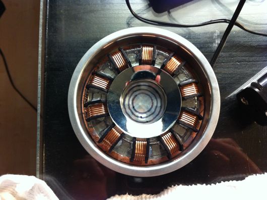
Completed RT Mark II arc reactor

Toward the end (which was the night before the first Halloween party I had to go to, I decided to make that center lens with sanded lexan and hand-drawn concentric circles. The one in the movie had a cool ridged lens like those on a lighthouse lamp. I ran out of time and patience and this is the compromise. :)

On to the steps I took, shall we?

First, I drew up plans. I'm not much of a planner, but something this weird needs some kinda goal. Dr. Stephen Covey says to start with the end in mind. Smart man. I couldn't have winged/wung/wanged this one.
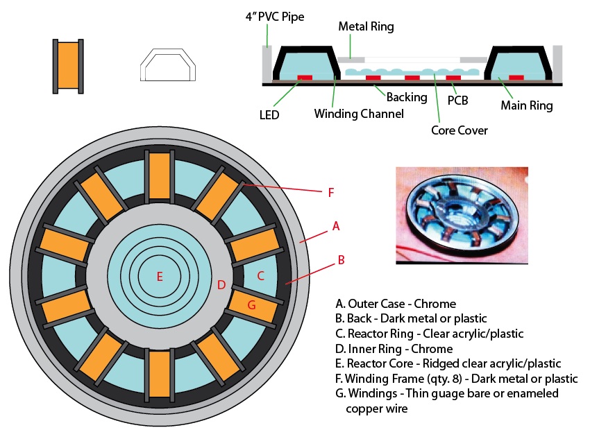
Plans for my arc reactor

I drew the plans to-scale in Adobe Illustrator. I took this sheet with me to Home Depot, Michaels, Target, etc. to find parts to fit. Most of that hunt went well, save for the stupid big clear plastic ring with the copper windings around it in ten places. That's where this turned into a learning experience, as well.

Let's start with the worst part of this build, which, based on my lack of talent and knowledge in electronics, should have been the electronics. It was not. The worst part was that damn plastic ring. I've watched enough Mythbusters and on-line crafting and DIY videos to know that you can "easily" cast your own parts at home. "Easily" is a term I now use sparingly and loosely when it comes to my DIY/maker/tinker projects.

To mold a part, you have to have an original. How hard could it be to make a ring? I can cut wood, sand it, make it pretty darn smooth and shiny and nice. Attempt at making a ring original was done in wood. It sucked. My old, worn out hole saws (big circular drill bits that cut large diameter holes in things) butchered the hard wood I was trying to cut the ring out of. Usually, I can handle a rough cut and can clean up after it. This was beyond reparable. I didn't even bother to take photos. I still have it, though. Lesson learned.

Yucky wood ring attempt

Second attempt was bending acrylic rods. Can you say bubbly? Can you say distorted? Can you say FAIL?

Bending acrylic = Bleh

Third time was a charm. I ran to Michaels and bought Sculpey polymer clay. It's very cool stuff. You make a thing out of it and bake it for 15 minutes at 275° (I recall) and it becomes hard and sandable and carvable and all that jazz. Awesome stuff. I formed the ring as a long rod, first. Gave it its profile shape using some aluminum straight edges and my level, then bent it around to fit the plans I had been carrying around. I trimmed the extra length off and smooshed the ends together and smooth all of it out. It looked rough, but workable. I baked it. I sanded it and shaped it into a pretty darn good first-ever Sculpey part:

Polymer original for reactor main ring

I used a heavy bearing as a sort-of rolling pin to help shape the ring. A razor was handy and the straight edge things were perfect:

Tools of the trade

The next step, at least from what I've been reading, was to layer a bunch of latex over this thing to make a mold from which we will eventually make a clear epoxy resin ring.

Seal around the bottom

Suggestions from a number of experts say that you should glue your part to a non-porous surface and seal the gap under it with clay or something similar. I did. It was a good call, too.

Next, layers and layers of latex are painted over the part until a fairly sturdy but flexible rubbery mold was built up:

Layers of latex

Each layer needs to be dry before the next on goes on. It was tedious, but very cool when finished.

Finished latex mold

Reminder: I suck at casting and mold making. Do not follow my lead. I scraped by on this one. The image above was my second attempt because I ignored some recommendations in the first try. Buh-bye, time. This one shown above, though, was great! But, like the videos will show you on-line, you need a, "mother mold" made of something sturdier to help the latex mold keep its shape. I did that with plaster of Paris:

Plaster of Paris from DAP

You can get a bucket like this one at Michaels for cheap. A few bucks. While the latex mold was still sitting on the original in the pyrex dish, I glopped on the plaster, which I mix slightly thicker than usual to help it stay in the shape I made it:

Completed mother mold

It worked great. It was perfect, but it was good enough to cast resin thingies.

The next step was to carefully follow directions and mix clear epoxy resin with activator and pour that into this mold. That's great, in theory... Following directions, that is. I was interrupted while counting drops of activator and didn't get enough in the resin goop. I also did not sir it vigorously enough and even properly, according to directions I'd watched three or four times on YouTube. Like the silly latex mold thing, I had to do the resin casting twice. Sadly, neither was great. The second attempt was at least workable for this project.

Clear epoxy resin in latex mold

The above photo is of the second casting. Sadly, the mold was slightly gooed up by the first casting. The second was the right ratio of activator and resin and would have been awesome, but the outer surface stayed tacky for a while because it did not fully cure. Luckily, it didn't affect the overall finished product too much. Since the silly prop was going to be under my shirt most of the time, nobody would notice the craptastic casting job I did.

Here is the final part:

Final clear epoxy resin reactor ring

The texture was from me trying to impart a texture with a paper towel. It kinda worked, but mostly didn't. It's OK, though. The ring does a great job of scattering the ridiculously bright blue light from the LEDs in the final product.

The next step was to build the copper windings that are on the main reactor ring (the clear thing above). This seemed like a pretty straightforward process until it came time to actually do it, of course. I ordered some c-channel ABS model railroad strips from Plastruct. They are perfect, but there are 5 tiny parts for each of the 10 locations around the ring. Cutting those little parts was ultra-tedious and highly inaccurate and inconsistent. I had planned to cut the angles and to use model glue to build them ahead of time and then simply stick them onto the ring. Ha! Funny.

So, plan A for the windings was a FAIL. Plan B was to carefully heat the c-channel stuff and to bend it over the ring. FAIL again. It mostly just curled up and got bubbly, even with low heat. Plan C was to cut each side of the winding channels from thick, black cardboard or Sculpey (and then bake the Sculpey). During another of many trips to Michaels, I bought a sheet of photo matt stuff. It was fairly thick, I could cut it with an Exacto, and I could paint it or Sharpie it. This didn't seem horrible, at first. But, it was one of the most tiring and laborious parts of this build. Look at the parts laid out on the cutting mat:

Reactor ring winding channel sides

These were cut from a strip and I used a template drawn in Illustrator for shape them. At this point (in the photo above), they were easy to work on. The next step was the crappy part: Cutting the insides out of them:

Steps in making each of the 20 channel sides

I went through about 4 or 5 Exacto blades cutting these shapes. My hands were killing me by the time I finished. They also had to be painted all black with a Sharpie. This particular cardboard is matte for a photo or painting. It is black on one side only.

Now that the channels were ready to keep the windings in place, it was time to do the actual windings. I purchased two pounds of 22 gauge and 24 gauge bare copper wire for this. The idea had the potential to look awesome and authentic. The first and only true copper winding took about an hour. Forget that racket. Let's think more like a low-budget Hollywood prop make would... Think, think, think... I was up until about 1:30 that night and gave up on a solution. Here is the awful real copper winding:

Yucky real copper winding

The next morning, I came up with the idea that would save me countless hours of carefully wrapping copper wire around a sticky resin ring: Cut small strips of old IDE hard drive ribbon cables and kink them to the profile shape of the ring. Genius, if I do say so myself:

IDE ribbon cable as copper windings

The only thing they ribbon cable bits needed was a nice coat of copper paint. Testors makes a great copper paint, as you can see:

Genuine simulated copper windings

Now, before I move past the windings, how they're held onto the ring is another bit of niftyism: I drilled holes through the ring so that I could take some of that two pounds of bare copper wire and stick it through the ends of the ribbon cable and lock them in place:

Fastening the windings onto the ring

Also, while the outer surface of the ring was tacky, thanks to my complete lack of casting skizillz, I carefully wrapped the edges of the ring with tin foil, shiny side inward to help bounce the blue light around more inside the resin:

Tin foil reflector things

The only thing left on this whole copper winding fiasco was to glue the channel sides onto the ring along each side of each winding:

Winding channel sides glued on

Since I was running out of time, I didn't do this as cleanly as I would have liked. Upon close inspection, it looks atrocious. But, on shelf or under a shirt, nobody is none the wiser more none... Er... Yes. How about that copper paint?!

Earlier in the build process, I had to make the outer ring. In the movie, this was the container embedded in Tony's chest that held the reactor. I used ABS plastic pipe, cut a 1/2-inch slice with the band saw, and painted it with chrome(-esque) paint:

Outer ring from 3-inch pipe

The center chrome ring was a drain thing I found at Home Depot:

Drain thing from Home Depot

I cut the threading off and ground down the flange to the proper diameter for the center of the reactor.

The last hurdle was how to wear the silly reactor. My wife, in a flash of brilliance, suggest we Velcro the thing to my undershirt. Well, prior to that, I hadn't thought of wearing a shirt under my shirt. The final reactor had black felt on its back to make it more comfortable against my chest. To accommodate the Velcro idea, I just hot-glued the fluffy half of some Velcro pads to the back of the reactor:

Fluffy side of Velcro on back of reactor

Then, I sewed the hooky side of the Velcro pads to the front of a wife-beater shirt:

Hooky Velcro pads on shirt

Completed kit, Velcro on shirt

I'll be wearing the wife-beater under a thin white long-sleeve casual shirt. The reactor is still incredibly bright under even a dark brown t-shirt:

Clearly visible, even with a flash and dark brown shirt

Here is the reactor turned on:

RT Mark II arc reactor replica powered up

It's silly how bright it is. Should make for great conversation at the parties.

My Very Own Useless Machine Ever!!! (Finally!)

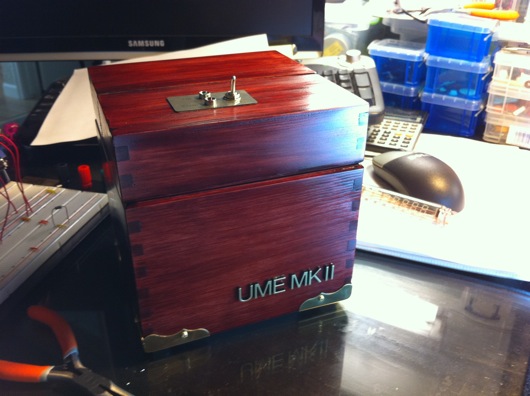
I finally finished my own UME Mark II for my own desk for me! Woohoo! My flavor of useless machines ever has a "presidential" look, as some have put it. Latest UME Mk II

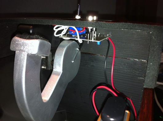
This latest model is the first version of the UME Mk II that incorporates a small PCB (printed circuit board) underneath the lid that is attached directly to the pins of the On/Off switch and the two LEDs. It has all the discrete components required to drive the modified servo. It saves time in soldering and it tidies up the wiring under the hood of this magnificent machine.

UME Mk II PCB v1

The wiring that is there comes from the servo, the "parking" switch, and the battery. The next machine I make will have slightly better placement of the board relative to the arm. The clearance was a little tight for my taste, but it still turned out great. This first version of the integrated PCB required some hand-tweaking. I had to cut a couple traces, solder a couple of jumper wires, and notch a little corner out of the board to allow clearance for the parking switch.

The parking switch is the little microswitch inside the box that the arm trips when it retracts back into the box. Its purpose is to cut power on the back swing of the arm. When you flip the On/Off switch to On on the top of the machine, you give power to the circuit and the arm releases the parking switch. When the arm moves the On/Off switch to Off, it actually reverses its own direction. It then heads back into the box until it presses the parking switch, which cuts off power again.

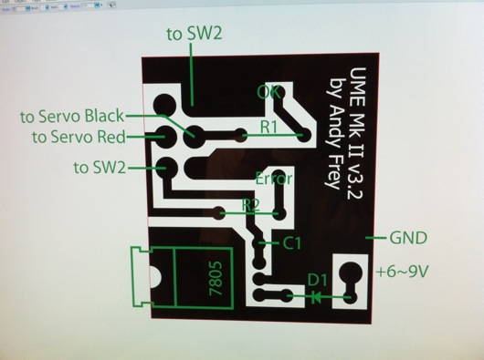
UME Mk II PCB Diagram

The "3.2" version number is truthful: I revised that silly drawing about 3.2 times. The one above is the latest that incorporates the cuts in the traces I had to make on my machine's PCB. It also takes into account the trimming I did in one corner of the board. In the diagram, I just trimmed the entire edge so that it was still rectangular and easier to cut out.
Everywhere you see black is where there would be copper left on the PCB when etching is completed. The green lines and labels are there for reference but are not printed on the final PCB. The white lettering in the black gets etched out of the copper on the PCB. The little circles at the ends of the traces and a few other places in the black areas are drilled with little bits under my drill press. The final PCB turns out nicely, for a home-brew board, I think.
DIY Workshop Stereo Boombox Kinda Thing

A car stereo, some extra car stereo speakers, some hardwood, and a ATX power supply for a computer and SHAZAM! You get a garage stereo that can play your iPod, XM radio, CDs, and AM/FM radio. This project was easy and only a little tedious to make. It was fun and it sounds awesome. Plus, the little speakers I had in my garage cabinet are not the greatest, but they're not bad. With a 500 or 600 watt power supply, I can beef it up someday if I get the energy.