UPDATE: Want a PCB and components for your own project? I've had a deluge of requests for the PCBs for this project. If you're interested, please contact me through this blog. I'm trying to figure out whether it's worth it to sell the boards alone or maybe as a kit with the LEDs and resistors (or current limiting devices) or maybe even assembled (LEDs, resistors and power leads). I have been dying to post photos of my latest colossal time-sucker-of-a-project: My Halloween 2010 costume is Tony Stark. Iron Man would have been a pain in the mechanical arse, but Tony Stark's only challenge is that crazy super-glowy round life-saving thingy thing in his chest which is visible under a shirt. This is the most ridiculous and complicated build I've done to date.
This post is about building the arc reactor Tony Stark needed to survive in the Iron Man movies. The particular version I wanted to build was the RT Mark II, which Tony built in his home lab once he got home from his captivity in the desert. It's more refined than the first version he built in the cave and every bit as swanky. Mostly, I liked the look of the second one better, myself. The one I'm talking about can be seen in the movie fairly up-close when Pepper Potts has to remove the old one and replace it with this new one.
So, first thing's first... I had to create a round circuit board (and a circuit, for that matter) with some super-bright LEDs that wouldn't catch fire under my shirt and, at the same time, would be visible from space from under my shirt. Ideally, I wanted this thing to stay fairly bright for as long as possible, like, say, a long night at a Halloween party. I'm just sayin'... I shopped around at SuperBrightLEDs.com and found some 5mm square surface-mount LEDs. These little doods have THREE little ultra-bright LEDs in each little 5 mm X 5 mm X 1.5-ish mm package. The blue ones that I used in the were so bright that when properly powered, they left greenish-yellowish spots in my vision for a while after looking at them.
I wanted the PCB to be functional, of course. It needed to properly connect the parts of the circuit together. But, I also wanted the traces to look movie-like. Busy, complex, important, and artsy at the same time. I design the circuit in Illustrator and tried my best to make the traces look like they were more than just power for LEDs:
You can see that the PCB design even includes the Stark Industries logo at the top. The zig-zaggy parts are the landing pads for the SMD LED packages. They have three anodes on one side and three cathodes on the other. I ran each SMD LED package's individual LEDs in series. There are 14 total SMDs, or 14 total three-LED series circuits. Each of the 14 series LED circuits connects to the ground bus (the outer ring in this design) and +9.6 volts via the center "C" ring. The little squares are the through-holes for the 15-ohm resistors for each of the 14 SMDs. The final etched board looks like this:
The fuzzy edges and weird texture on the traces are due to some craptastic refurb toner cartridges I bought for our HP 2600n color laser printer. The black cartridge deposits a funky pattern of toner all over the page. This translated to the pattern being transferred onto my PCB. To make PCBs, BTW, I use the toner transfer method. The products I use are from Pulsar and their stuff works AWESOME. I never imagined I'd be able to create my own circuit board this easily and with such accuracy. I bought the laminator they recommend using. The laminator came in handy for the our badges to the 2010 Stark Expo:
I am going as Tony Stark, including growing a goatee and moostash:
My wife is going as Pepper Potts and coincidentally looks just like her.
Here is the completed board with parts populated:
Now, on to the power supply...
Before I get too far, the power supply for this thing is an 8-pack of NiMH AA batteries and pumps out about 9.6 volts. The batteries are Energizer rechargeables that are labeled as having approximately 2,300 mAh of power in them. As you'll see later on, there are a total of 14 SMD LEDs on my circuit board. Each of those LEDs is actually THREE LEDs and each of those LEDs uses 3.2 volts and draws 20 mA of power. I ran each of the internal LEDs in each of the SMD LED packages in series, so (forgive me for being a complete n00b electronics geek) each SMD should draw 20 mA of power and drop 9.6 volts across the entire package. For safety, I did stick a 15 ohm resistor in front of each SMD. But, because I'm not too concerned about the nitty-gritty, I figure that 14 SMDs (14 x 3 LEDs) each drawing 20 mA equates to 280 mA. 2,300 mAh of battery power should light the arc reactor for upwards of 8 hours, but in reality, it will croak much sooner. So, in order to keep my glowing chest entertaining, I'll carry two sets of 8 fully charged AA batteries. If I'm out later than the productive life of those batteries, I'm probably going to be in rough shape the next day.
OK, back to the LEDs... Here is a picture of one of them:
That one might be white. I can't remember. But, they're tiny and bright and that's all that matters.
Did I mention that they're tiny and they're surface-mount? I hadn't tried SMD, up to this point in my inexperienced little electronics hobby career. In person, the work I did got progressively better and you can see it on the completed circuit board. Or, maybe you can't because it's hot-glued into the completed project. Anyhoo... I did perfect getting those little things onto a circuit board. It's pretty easy, once you figure it out.
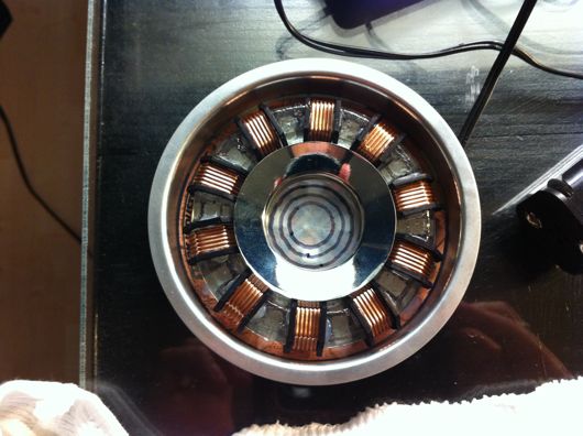
So, here is the completed arc reactor, for those of you who don't care to read the ramblings about building it:
Toward the end (which was the night before the first Halloween party I had to go to, I decided to make that center lens with sanded lexan and hand-drawn concentric circles. The one in the movie had a cool ridged lens like those on a lighthouse lamp. I ran out of time and patience and this is the compromise. :)
On to the steps I took, shall we?
First, I drew up plans. I'm not much of a planner, but something this weird needs some kinda goal. Dr. Stephen Covey says to start with the end in mind. Smart man. I couldn't have winged/wung/wanged this one.
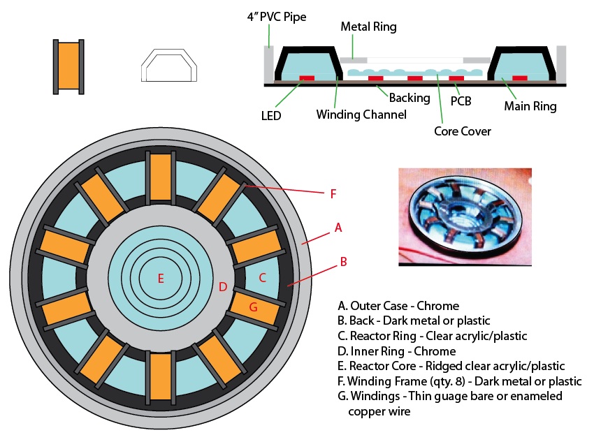
I drew the plans to-scale in Adobe Illustrator. I took this sheet with me to Home Depot, Michaels, Target, etc. to find parts to fit. Most of that hunt went well, save for the stupid big clear plastic ring with the copper windings around it in ten places. That's where this turned into a learning experience, as well.
Let's start with the worst part of this build, which, based on my lack of talent and knowledge in electronics, should have been the electronics. It was not. The worst part was that damn plastic ring. I've watched enough Mythbusters and on-line crafting and DIY videos to know that you can "easily" cast your own parts at home. "Easily" is a term I now use sparingly and loosely when it comes to my DIY/maker/tinker projects.
To mold a part, you have to have an original. How hard could it be to make a ring? I can cut wood, sand it, make it pretty darn smooth and shiny and nice. Attempt at making a ring original was done in wood. It sucked. My old, worn out hole saws (big circular drill bits that cut large diameter holes in things) butchered the hard wood I was trying to cut the ring out of. Usually, I can handle a rough cut and can clean up after it. This was beyond reparable. I didn't even bother to take photos. I still have it, though. Lesson learned.
Second attempt was bending acrylic rods. Can you say bubbly? Can you say distorted? Can you say FAIL?
Third time was a charm. I ran to Michaels and bought Sculpey polymer clay. It's very cool stuff. You make a thing out of it and bake it for 15 minutes at 275° (I recall) and it becomes hard and sandable and carvable and all that jazz. Awesome stuff. I formed the ring as a long rod, first. Gave it its profile shape using some aluminum straight edges and my level, then bent it around to fit the plans I had been carrying around. I trimmed the extra length off and smooshed the ends together and smooth all of it out. It looked rough, but workable. I baked it. I sanded it and shaped it into a pretty darn good first-ever Sculpey part:
I used a heavy bearing as a sort-of rolling pin to help shape the ring. A razor was handy and the straight edge things were perfect:
The next step, at least from what I've been reading, was to layer a bunch of latex over this thing to make a mold from which we will eventually make a clear epoxy resin ring.
Suggestions from a number of experts say that you should glue your part to a non-porous surface and seal the gap under it with clay or something similar. I did. It was a good call, too.
Next, layers and layers of latex are painted over the part until a fairly sturdy but flexible rubbery mold was built up:
Each layer needs to be dry before the next on goes on. It was tedious, but very cool when finished.
Reminder: I suck at casting and mold making. Do not follow my lead. I scraped by on this one. The image above was my second attempt because I ignored some recommendations in the first try. Buh-bye, time. This one shown above, though, was great! But, like the videos will show you on-line, you need a, "mother mold" made of something sturdier to help the latex mold keep its shape. I did that with plaster of Paris:
You can get a bucket like this one at Michaels for cheap. A few bucks. While the latex mold was still sitting on the original in the pyrex dish, I glopped on the plaster, which I mix slightly thicker than usual to help it stay in the shape I made it:
It worked great. It was perfect, but it was good enough to cast resin thingies.
The next step was to carefully follow directions and mix clear epoxy resin with activator and pour that into this mold. That's great, in theory... Following directions, that is. I was interrupted while counting drops of activator and didn't get enough in the resin goop. I also did not sir it vigorously enough and even properly, according to directions I'd watched three or four times on YouTube. Like the silly latex mold thing, I had to do the resin casting twice. Sadly, neither was great. The second attempt was at least workable for this project.
The above photo is of the second casting. Sadly, the mold was slightly gooed up by the first casting. The second was the right ratio of activator and resin and would have been awesome, but the outer surface stayed tacky for a while because it did not fully cure. Luckily, it didn't affect the overall finished product too much. Since the silly prop was going to be under my shirt most of the time, nobody would notice the craptastic casting job I did.
Here is the final part:
The texture was from me trying to impart a texture with a paper towel. It kinda worked, but mostly didn't. It's OK, though. The ring does a great job of scattering the ridiculously bright blue light from the LEDs in the final product.
The next step was to build the copper windings that are on the main reactor ring (the clear thing above). This seemed like a pretty straightforward process until it came time to actually do it, of course. I ordered some c-channel ABS model railroad strips from Plastruct. They are perfect, but there are 5 tiny parts for each of the 10 locations around the ring. Cutting those little parts was ultra-tedious and highly inaccurate and inconsistent. I had planned to cut the angles and to use model glue to build them ahead of time and then simply stick them onto the ring. Ha! Funny.
So, plan A for the windings was a FAIL. Plan B was to carefully heat the c-channel stuff and to bend it over the ring. FAIL again. It mostly just curled up and got bubbly, even with low heat. Plan C was to cut each side of the winding channels from thick, black cardboard or Sculpey (and then bake the Sculpey). During another of many trips to Michaels, I bought a sheet of photo matt stuff. It was fairly thick, I could cut it with an Exacto, and I could paint it or Sharpie it. This didn't seem horrible, at first. But, it was one of the most tiring and laborious parts of this build. Look at the parts laid out on the cutting mat:
These were cut from a strip and I used a template drawn in Illustrator for shape them. At this point (in the photo above), they were easy to work on. The next step was the crappy part: Cutting the insides out of them:
I went through about 4 or 5 Exacto blades cutting these shapes. My hands were killing me by the time I finished. They also had to be painted all black with a Sharpie. This particular cardboard is matte for a photo or painting. It is black on one side only.
Now that the channels were ready to keep the windings in place, it was time to do the actual windings. I purchased two pounds of 22 gauge and 24 gauge bare copper wire for this. The idea had the potential to look awesome and authentic. The first and only true copper winding took about an hour. Forget that racket. Let's think more like a low-budget Hollywood prop make would... Think, think, think... I was up until about 1:30 that night and gave up on a solution. Here is the awful real copper winding:
The next morning, I came up with the idea that would save me countless hours of carefully wrapping copper wire around a sticky resin ring: Cut small strips of old IDE hard drive ribbon cables and kink them to the profile shape of the ring. Genius, if I do say so myself:
The only thing they ribbon cable bits needed was a nice coat of copper paint. Testors makes a great copper paint, as you can see:
Now, before I move past the windings, how they're held onto the ring is another bit of niftyism: I drilled holes through the ring so that I could take some of that two pounds of bare copper wire and stick it through the ends of the ribbon cable and lock them in place:
Also, while the outer surface of the ring was tacky, thanks to my complete lack of casting skizillz, I carefully wrapped the edges of the ring with tin foil, shiny side inward to help bounce the blue light around more inside the resin:
The only thing left on this whole copper winding fiasco was to glue the channel sides onto the ring along each side of each winding:
Since I was running out of time, I didn't do this as cleanly as I would have liked. Upon close inspection, it looks atrocious. But, on shelf or under a shirt, nobody is none the wiser more none... Er... Yes. How about that copper paint?!
Earlier in the build process, I had to make the outer ring. In the movie, this was the container embedded in Tony's chest that held the reactor. I used ABS plastic pipe, cut a 1/2-inch slice with the band saw, and painted it with chrome(-esque) paint:
The center chrome ring was a drain thing I found at Home Depot:
I cut the threading off and ground down the flange to the proper diameter for the center of the reactor.
The last hurdle was how to wear the silly reactor. My wife, in a flash of brilliance, suggest we Velcro the thing to my undershirt. Well, prior to that, I hadn't thought of wearing a shirt under my shirt. The final reactor had black felt on its back to make it more comfortable against my chest. To accommodate the Velcro idea, I just hot-glued the fluffy half of some Velcro pads to the back of the reactor:
Then, I sewed the hooky side of the Velcro pads to the front of a wife-beater shirt:
I'll be wearing the wife-beater under a thin white long-sleeve casual shirt. The reactor is still incredibly bright under even a dark brown t-shirt:
Here is the reactor turned on:
It's silly how bright it is. Should make for great conversation at the parties.


