If you're like me, and I know I am, you have spools of wire or solder sitting around. I generally put mine in the cabinet above my desk. Lately, with more projects going on, I find myself pulling them down out of the cabinet constantly. I had a collection of the most used spools sitting on the workbench cluttering it up. Well, no more, I say! Here's how I organized them and made it easier to pull pieces from them quickly.
How To Compete in Your Company's FitBit Walk Competition While Injured
I built a machine to walk my FitBit for me. I call it the FitBit Cheat-O-Matic! Why? Our office is having a FitBit competition this month (November 2013). In preparing for the competition I overworked my Achilles tendon and could not participate. So, I adopted the mantra:
If you can't join 'em, beat 'em.
The FitBit Cheat-O-Matic is a machine that shakes my FitBit for me 24 hours a day, 7 days a week and does it faster than my normal walking pace. I suppose it's actually faster than most people can run, for that matter. Sure it's cheating! Not only is it cheating, but it's cheating at a level that's so blatant it can't be mistaken for anything else! It's fully disqualified from the competition, of course. But the point is no longer to win the competition, but to be totally ridiculous and to rack up outrageous FitBit stats and make people laugh or maybe shake their heads.
Standing Desk Improvisation Inspiration with Little Perspiration
Today at the office, I walked by a coworker's desk and something was different: She'd put an Ikea table and shelf together and set them on top of her desk. Nutty, at first glance. Purposeful, after 0.25 seconds of thought. Here's the story of what I saw: Inexpensive IKEA furniture repurposed for other ingenius uses.
Electronics Workbench LED Upgrade
I guess I forgot to post an update to the update of my workbench. Not only did I clean up the gigantic mess that had accumulated on it, I improved the lighting and workspace availability:
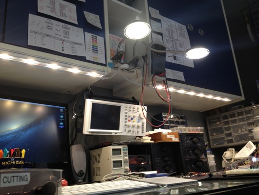
Prior to this upgrade, I had fluorescent lighting under the blue cabinets over the bench. They extended down about 3 to 4 inches and kinda got in the way. I also didn't think through the placement, so they were back about half-way under the cabinets. This meant they didn't put light out on the front edge of the tabletop like I would have hoped. Here's the old lighting:
The monitor on the left barely fit behind the light and the light extended down lower than the top of the monitor. Dumb. I might have been drinking bourbon that day. Like, more than a shot or two. No matter. That is history. Today, we have wonderLEDs!
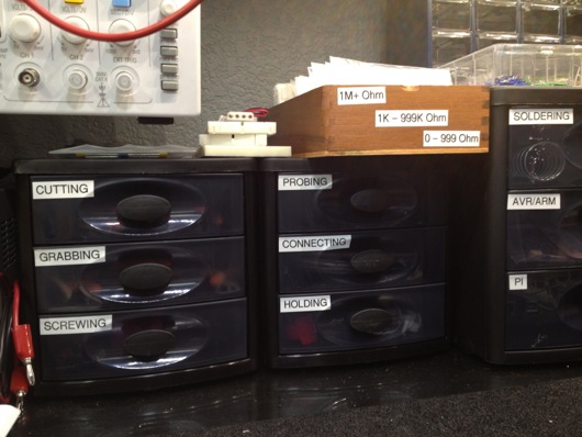
Also, notice I suspended my oscilloscope above the desktop. It freed up quite a bit of desktop space. I added some more plastic storage drawers to organize my tools and miscellaneous other parts that usually wound up spilled all over the work mat. I labeled the drawers for quick searching and fun:
I believe I found those at Target. They were inexpensive and they work very well. They have little rubber footies to keep them from sliding around on the glass tabletop when opening and closing the drawers. As you can see, it's easy to tell what's in each drawer... If you're me. My wife needed a few seconds to interpret the labels in order to find the scissors. Scissors cut things. They're for, "cutting." BOOM! Easy-peasy lemon squeezy.
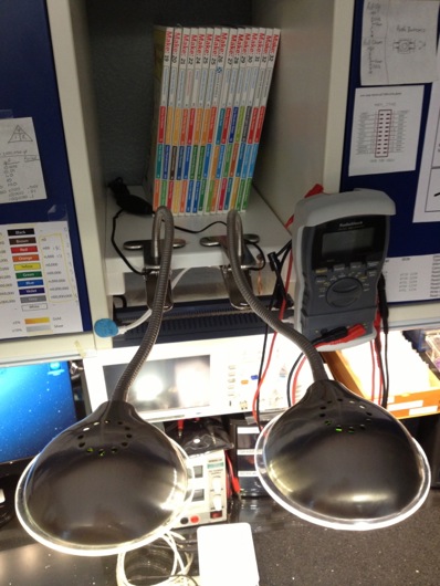
I picked up the two LED bars under the cabinets and the two gooseneck LED lamps at Lowe's (maybe Home Depot, can't remember). All told, I maybe spent $100. The best thing about the bars is that they're quite flat, leaving plenty of headroom for monitors and whatnot. The two flexible lamps clamp onto the little shelves I built between the cabinets:
These are about $20 each. They put off great light, stay cool and I can point them individually to light a component any way I like.
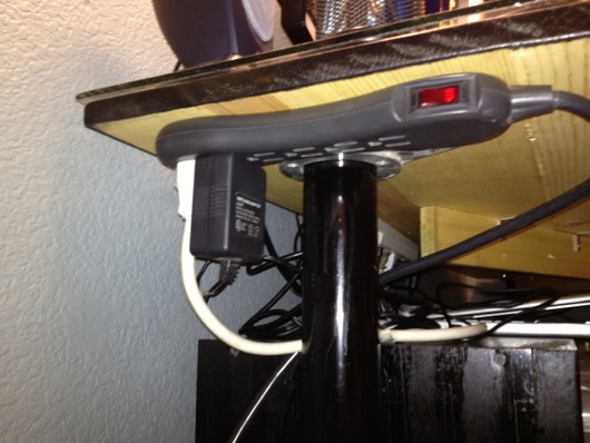
I set up the power to go through a single multi-outlet toward the back and under the ledge of the workbench table top (please excuse the fuzzy photo):
It's an easy reach to turn the lights on and off. The two gooseneck lamps have their own switches on the shelf above, so it's easy to switch them on or off without taking down all the lights.
Lipstick Camera Turned Video Microscope
Backstory: In a previous life, I was a freefall photographer. I took photos and shot video while skydiving. Before GoPro and others started popping up on the scene, I had devised a little rig for shooting freefall video without the need for the bulky miniDV camera on my helmet. The setup used a "bullet" or "lipstick" camera which provided a video input signal for a miniDV camera (used as a tape deck at this point) located OFF my helmet and in a pouch under my jumpsuit. I don't remember where I got the camera. They can be found on the InterWebs for $100-ish, maybe less. Anyhoo, if you've ever stuck your hand out of the window of a car moving at highway speed, I'm pretty sure you'll be able to figure out how non-aerodynamic a miniDV camera is. Needless to say, a lipstick camera cuts through the wind WAY easier than a full-on Sony TRV-20 miniDV camera. A lipstick camera also weighs considerably less than a miniDV camera.

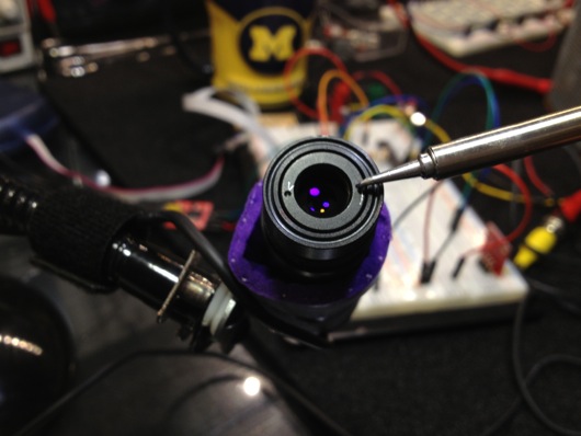
OK, now that I've barfed out a giant intro paragraph, let's get to the nutty-tasting inside of this story: I have this lipstick camera sitting around in a box. I know that when I twist the lens away from the sensor, the camera acts more and more like a video microscope. I have many tiny things I'd like to look at with minimal camera shake.
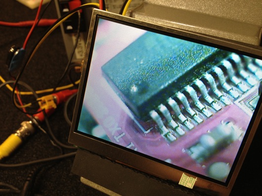
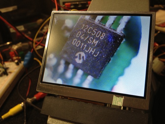
Neato. In fact, this thing is an excellent tool for reading the tiny, tiny lettering on tiny, tiny surface mount devices ("SMDs") on tiny, tiny circuit boards that I am studying. The problem is holding it steady enough and having a free hand (two is even better) to move around the object under study and take notes. (There are more samples at the end of this article.)
My eyes are pretty good considering the amount of time they spend staring at computer screens and my age, but occasionally I run across some parts or circuits where there is no way I can easily read the tiny print without magnification. The image above is coming from the lipstick camera and is being shown on a 3.5-inch NTSC/PAL TFT monitor I picked up at Adafruit Industries.
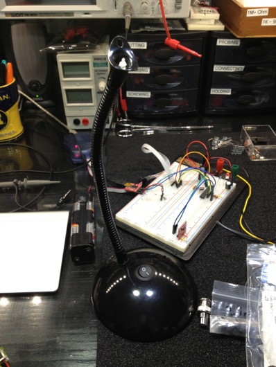
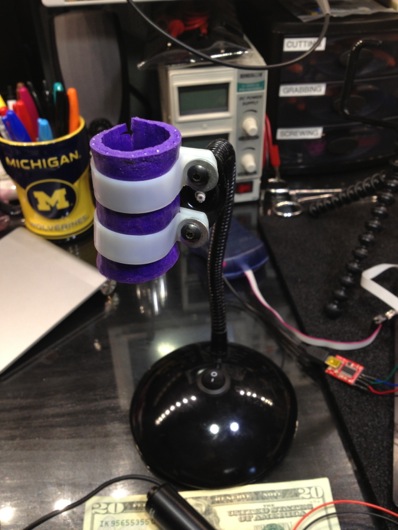
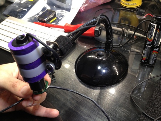
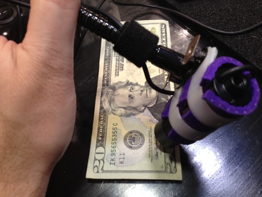
Holding the camera sounds like a job for a gooseneck from a cheap lamp. Thanks, Ace Hardware! Got one. $12. Unscrew some parts, gut some stuff and boom! Microscope camera stand:
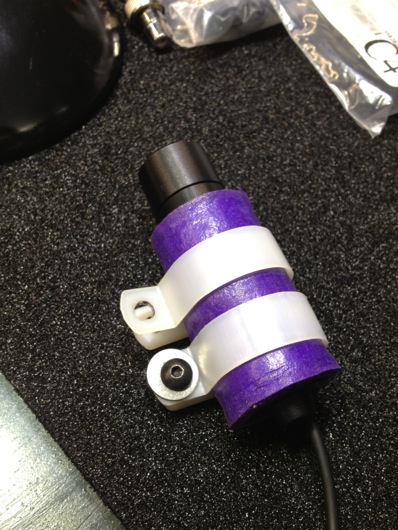
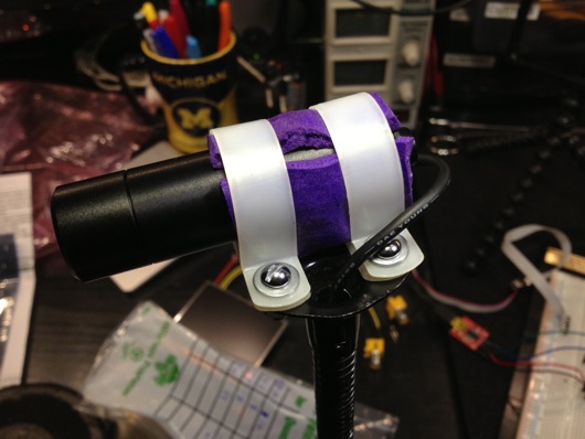
I repurposed some of the DIY mounting hardware I used to keep the little camera on my skydiving helmet. Two plastic brackets and some screws from Home Depot (as I recall) and a piece of yoga mat to grip it better, as it was flying with me through 120+ MPH winds.
I adapted it to the gooseneck lamp by flattening the bracket on the end of the gooseneck and simply screwing the brackets into it.
That was attempt number one, anyway. I routed the cable for the camera, which includes its video signal and power wires, down the gooseneck. The power and video out connectors are routed out of the lamps power cord hole. I dug through my prodigious collection of random screws, nuts and washers and found some #6 pieces that worked like a charm:
Here are some things I looked at with my nifty video microscope:
The device pictured above was used on my skydiving helmet to turn the Sony camera on and off. I can't remember its name anymore. It was very cool. It had a multi-color LED that was fixed to my eyepiece for targeting the camera in freefall. I could get status from the camera, like when it was running low on fuel and tape. The single button make it super easy to work. Prior to devices like that, you had to have someone tell you that the red record light was on before climbing out of the plane.
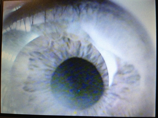
That image makes my iris look blue or grey, but it is in fact greenish-brown. Taking a picture of an LCD with my iPhone doesn't really keep a color profile intact, of course.
That resistor is a 1/4-WATT, regular old resistor you've put in a thousand projects. The little dood next to it is the tiniest SMD LED I've ever seen. I had purchased and bunch of those little guys for a clock project and had no idea just how freaking tiny they were until I got them in-hand. No. Way. On. Earth. ...Am I gonna figure out way to solder those puppies to something and make them work. Funny thing about that particular one pictured above: I had lost it for months. While I was putting this microscope together, it just showed up next to another not-quite-as-tiny SMD LED I was examining. I think it was stuck to the edge of the ESD foam on my table and just dropped off by coincidence. It's blue, if you're wondering. Intensely blue with 3 volts.
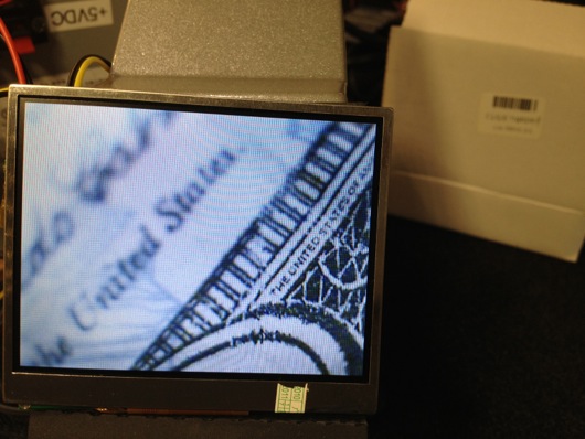
Currency is always fun to scope.
So, the next step in this project will be to make the LCD look nice and maybe conveniently mount it to the base of the scope. I dunno, yet. I have two of these little LCDs and each of them has two inputs. I might use the other one for a forward-looking camera on my RAM 1500 truck. Who knows?
Electronics and Hack Workbench
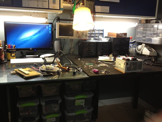
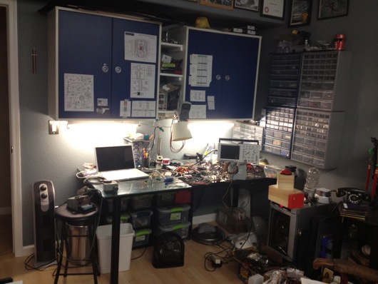
I've had a number of requests from readers to see my workbench in its entirety, as most photos of it are just backgrounds to projects. So, I thought I'd post some photos and explanations in an article. Maybe someone will get some helpful hints or perhaps someone will lend me some helpful advice. First off, here are some wide shots of the mess:
I made the table. The top is made out of three 10"-ish wide pine boards glued together side to side using biscuits. I had a custom piece of 3/16" glass to fit the top. Half of the top of the table is covered with conductive foam to keep static at bay. I ordered a couple big pieces of that from somewhere on-line, can't remember where. It's super convenient for stabbing parts into to hold them neatly. It's also great for discharging static. The legs I've had a while. They were part of a giant desk I built years ago. I got them on-line many moons ago. They have bases that are screwed to the bottom of the tabletop. They then screw into the bases. They're made of steel or aluminum or something strong like that. Under the tabletop, I put a big "X" of 3" wide interlocked pine planks for rigidity. I can stand right on the center of that table and it barely flexes.
Down below the desktop is a six-cubbyhole shelf on little rubber footies leftover from my table saw stand (that is now attached to a rolling platform I made). In each of those cubbies, I put plastic lock-top containers full of various larger items, like wall warts, scavenged PCBs from VCS and such, and cords. This is a great use of space that would otherwise be cluttered up with piles of things.
The blue cabinets came with the house. As with most of the light fixtures and some other miscellaneous pieces left behind by the previous owners, I'm guessing they're from Ikea. They're really handy. I added the little white shelves between the two cabinets. I have a benchtop digital power supply on the lowest shelf for easy access, but that's not my main power source. I'll get to that shortly.
I taped up a bunch of my most-referenced cheatsheets for things like pinouts on ATmega328's, ATtiny13's, common capacitor markings, resistor bands, ISP cables, etc. I also keep my DMM hanging right there and made a little wire hook for the leads.
The parts drawer cabinets on the right of the bench are typical types from Home Depot or Lowes. The more the merrier, as you can see. I keep groups of similar things close together. Eventually, there will be more of these. However, I have to get more creative with my space. To the right of the cabinets is a big painting that I commissioned for my Man Cave™ that I'd prefer not to move.
In some of the larger drawers, I use the conductive foam to hold my many ICs in layers to save space and for organization. I label each group with my handy Brother P-Touch labeler, like so:
Here's another angle on how I stack the ICs in the larger drawers:
I then put an index label on the front of the drawers so I can easily find families of ICs. I haven't yet found a really cool method for storing the 8 zillion resistors I have, but I do sort them by sub-1,000Ω, 1KΩm and 1MΩ drawers. Miscellaneous electrolytic caps are in one big drawer, common caps that are still in their tape from the manufacturer are generally sorted into smaller drawers.
I label the fronts of the drawers sometimes, especially when the drawer is clearly something that will always contain what it currently contains. In the case of my stacks of DIPs and whatnot, they very well organized.
I have so many parts, now, that I have built a spreadsheet to track them. A majority of the parts I have I've thrown on the end of orders because the parts looked cool or handy. When a grab bag of common transistors will only add a couple of dollars to an order, why not? AVRs are my favorite microcontroller, so I have a drawer dedicated to various renditions of that family of chip, as you can see on the middle left drawer above.
I don't know if people notice this in the background or in screenshots, but I use a 15" MacBook Pro for my benchtop computer. The battery failed, so it's always plugged into AC, now. It's now a flip-open desktop workstation, pretty much. I use this MacBook Pro to program microcontrollers and to have convenient access to the web and what not.
Our house is all Mac all the time. I have a Dell box used as a network storage server, but that's it. My regular desktop is a big-arse 27" 3.4 GHz iMac with a second 27" Cinema Display. Both are on wall-mount arms which are supposed to make my desk cleaner. However, as you can see in the photo below, all that's done is make more room for me to pile parts.
Of course, what desk area would be complete with a jackalope and an oil painting of a monkey in a fez?
About my primary power supply... I took apart a my wife's old computer that she had when we met. It was a sad, sad old computer I'd given her to get her by that I think I salvaged from my uncle's office. The power supply makes for a fantastic DC power supply. It provides very clean and reliable 3.3VDC/14A, 5VDC/22A, and 12VDC/10A power. This was crucial when I was working with peltier devices, which drew more amperage at their ideal voltages than the digital power supply could give them. This Dell power supply doesn't even break a sweat when a peltier device asks for 3.5A. The max on my digital PS is only a little shy of 3A.
I turn the supply on or off using this little toggle switch I rigged into the main jumper for the power supply.When I become ambitious about really finishing organizing my bench, I will snip all the extra wires and connectors and clean up the power supply. I'm also going to extend the voltage and ground leads and put nice ends on them to make it easier to connect and disconnect them from my many breadboards. Speaking of...
I whipped together this little adapter so that I could quickly connect and disconnect the various voltage leads from the power supply to my breadboards. I quickly got tired of screwing and unscrewing the thumbscrews on the breadboards when I wanted to switch them out. Eventually, these connectors will be on-the-ready toward the back of the benchtop and the switch for the power supply will be mounted more conveniently. The power supply will be relocated up and out of the way. Right now, sadly, it sits on two pieces of wood on the ESD foam.
When I work with my favorite microcontrollers, the AVR series from Atmel, I don't usually use a proper Arduino board, even though I tend to use the Arduino IDE. Instead, I whip together a quick circuit with either a 16 MHz or 20 MHz quartz crystal on a breadboard. I usually have three or so of these setup and ready to tinker with. I do actually have a few different types of Arduinos I've purchased with gift cards, recently. Here's an example of a typical setup for me:
I followed the recommendations from the ATmega328 datasheet for what components to put around it. There's a 10µH inductor on the analog voltage reference pin (in the photo above, it's on the Vcc pin, so ignore that). There's a 20 MHz quartz crystal on the XTAL1 and XTAL2 pins. Each of those pins is also connected to ground with 20 pF capacitors. Often times, I put a 7805 5V linear regulator on the + rails of ones side of the board and the other has either a 7812 12V regulator or LM10863V3 3.3V regulator on it. Of course, the proper capacitors near the regulators to clean up power are usually on there, as well. Don't forget the polarity diode so that you don't accidentally hook up the power supply leads backwards and cook something or popcorn an electrolytic capacitor.
As you can see from some of the above pictures and the one below, the edge closer to where I work on the glass surface gets cluttered with the parts I reuse the most.
About once every few months, I will clean up the area and put things back where they belong.
I keep my notes and diagrams and doodles in these awesome little Field Notes® brand notebooks with graph paper inside. They're about $10 for a 3-pack and each notebook has 48 pages in it. They're the perfect size to sit on the bench next to a project. Not so big that they require a lot of open space. Not so small that they're just not useful.
Last, but not least, I present my bourbon cabinet, complete with my hand-dipped (by me at the distillery) Maker's Mark® bottles. I have in my collection about 20 different bourbons. My goto at when we're out and about, of course, is Maker's Mark®. :)
That's it for the tour. If any of you have suggestions or comments, please, please leave them below in the comments section. I'd especially love to hear how you guys are storing your resistors. The ultimate trick still eludes me. I don't want to waste a little drawer for a single value, of course. Dividing up the drawers makes it too time-consuming to get one. I'm thinking along the lines of a Rol-O-Dex of resistors or something. I dunno. Comment away.
DODOcase "Smart Cover" Magnet Upgrade for iPad 2
AVR Serial Communications Using XBee RF Modules
I was contacted by Element 14 (Newark.com) recently about doing some product test drives using some of the products from their line card. I took two to three seconds to think about it. I know, tough one...
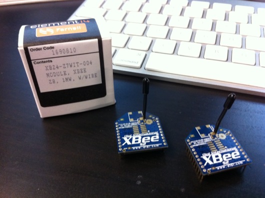
I have been chomping at the bit to use ZigBee wireless technology in a project. Digi International makes some REALLY cool and easy-to-use ZigBee RF modules that bring ZigBee technology down to a level that even I can implement without more than a few terse passes at a wireless book and a couple of datasheets. So, the first piece of loot I requested from Element14 was an XBee S2 module. I would love to link you to this module at Newark.com, but it appears to be gone. That is sad. BAck to our story... There was a spending limit on my test-drive loot. I ordered one XBee S2 module on my tab. The other XBee module was sent to me courtesy of Element14.com.
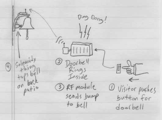
The ultimate project is based on a need at our house: We hang out on the back patio quite a lot and when we invite guests over, even after we ask them to just come on in, they ring the doorbell and we can't hear it out on the back patio. The leave disappointed that we would not be home when we said we would be. I'm kidding. Usually they do walk right in.
The first drawring I made used a brass marine-type bell with a string that was routed from the front door around to the back patio. Guests could simply tug on the string to get our attention. My wife wasn't keen on the network of pulleys and string required to make that happen. The drawring above is the watered down, no-fun-havin' version. Awe, who are we kidding? It's still fun. It's ALL fun! What's not to love about electricity and radio frequency waves making things do stuff??
Plan B for the remote doorbell is much cooler and much more electronic: Rig XBee to the house doorbell system so that it can signal a solenoid type of thing to plink a brass bell on the back patio. Not as Wallace & Gromit as the pulleys and string, but still pretty darn cool.
Oh, let me get this out early: Yes, übernerd, I know that XBee is overkill for a simple remote doorbell. The final version of this thing will use a simple little OOK (on-off key) RF module pair that simply sends on or off (button pushed or not). For now, though, this is a great way to get to know Señor XBee and his amigos.
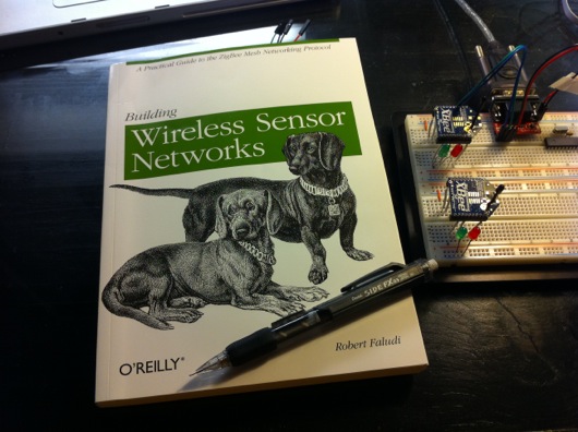
Before I go any deeper into this project, I want to HIGHLY recommend a book on the subject of AVR/Arduino microcontrollers and ZigBee networks. If you're interested in this stuff, go out and get a copy of Building Wireless Sensor Networks by Robert Faludi, published by O'Reilly. I also highly recommend you do NOT do what I did: Do not buy the book, read it cover-to-cover, and do absolutely nothing hands-on. I wound up having to re-read large portions of the book again to get my bearings with the XBee modules from Digi. Try to have an AVR microcontroller (or Arduino) and a couple of XBee modules on hand when you start reading the book.
Now, the first thing I have to say about these modules is that they are stupidly simple to setup and get running, as you'll see in this post. I was asked to do a write-up by Element14.com and this is an easy one: These are AWESOME. There are plenty of sources on the Web for connecting XBee modules. I won't go into major detail, but I will show you how quickly you can get to AVR microcontrollers talking wirelessly with two Digi International XBee S2 ZigBee RF modules. Keep reading...
The process for getting two XBee modules talking, or, in this case, two AVR microcontrollers talking via XBee modules, it this:
- Get two XBee modules (Farnell.com part 1690810) and a handful of 10-pin, 2mm headers used to adapt the non-breadboard-friendly XBee pins to your breadboard
- Get one or two AVR microcontollers with UART capability (and supporting components) or one or two Arduinos
- Build cheesy adapters for the XBee modules so that they fit your breadboards
- Download the X-CTU Windows program to upload newer firmware and appropriate firmware to the XBee modules (this relates to setting up one XBee module as the "coordinator" and one as the "router" [see book above])
- Put some serial-savvy code on an AVR chip or Arduino and connect its UART pins to one XBee module's DIN and DOUT pins
- Connect the other XBee module's DIN and DOUT pins to a serial cable to your computer
- Send commands through the air to the AVR from your favorite terminal program
OK, that's oversimplified, but if you're comfortable with building circuits and working with Arduino or AVRs, that's all there is to it. Take a look at this setup in action (and please forgive the hastily shot and edited video):
If you're a Mac person, and I know I am, you're going to disappointed in the lack of a Mac firmware updater for XBee modules. However, it is pretty darn simple to fire up Boot Camp or VMware and update the radios the way the aforementioned book suggests. I just picked up my breadboard with the two radios and the AVR and the USB-RS232 cable and plopped it on my desk next to my iMac and fired up VMware and did it. Nice and easy, save for one issue: Once the upload of the firmware was complete, Windows XP Pro went to a BSoD (Blue Screen of Death). Pretty awesome. Let me say that it is no secret that I hate Windows. I'm disappointed in Digi for note having a Mac client to update firmware on the XBee modules. Maybe someday...
If you follow the book, you can get two AVRs or a computer and an AVR communicating in pretty short order. The code I wrote for the AVR to receive the serial commands from the computer to switch the traffic LEDs was easy and it actually worked the first time. It's really cool when stuff works as advertised.
If you've got some communicating you need to do between your microcontrollers, especially multipoint stuff, XBee modules are the way to go. Soooooo easy to setup and use. Head over to Newark.com or your favorite source for Digi International products and start mesh networking your DIY gadgets.
This post was originally about the remote doorbell idea. I'll write a separate post about that completed project using simpler RF modules from SparkFun, as ZigBee is WAY overkill for a remote doorbell, unless you're putting little remote bells or buzzers all over your mansion.
Fix Missing Comments Problem in Notepad WordPress Theme
Some of you regulars may have noticed that comments were magically not appearing at the bottom of some of the posts on this blog. I snooped around in the code behind the theme and discovered one line of PHP that caused comments to sometimes show and sometimes not show. I'd like to share what I found to help others who are having the same problem. Let me add this little tidbit: I LOVE this Notepad theme by Nick La (http://ndesign-studio.com/wp-themes). His work is Very excellent. I contacted Nick through his contact form to let him know about the one-line fix to the comments.php file in his theme. I had installed this theme when my blog was running as WordPress 2-something, not 3.
Here is the easy fix: Edit your comments.php file and find this line (roughly line 24):
wp_list_comments('type=comment&callback=mytheme_comment');
Change it to this:
wp_list_comments(array('callback'=>'mytheme_comment'));
Update the file (save it). That should solve the issue.
DODOcase for iPad 2 DIY Magnet Upgrade
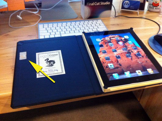
I LOVE my iPad 2. To protect it, I HIGHLY recommend the DODOcase (http://www.dodocase.com/products/dodocase-for-ipad2). My only complaint would be the lack of a magnet in the case to activate/deactivate the iPad through its little magnetic sensor, which is used by other cases, like the foldy-flippy one from Apple (http://www.apple.com/ipad/smart-cover/). What to do? Hack, of course! But, first, I emailed the DODOcase peeps and suggested the feature to them and even sent them links to my source of delicious rare earth magnets, K & J Magnetics (http://www.kjmagnetics.com/). There are thin little rectangular magnets that can easily be embedded into the cardboard cover underneath the backing.
For now, my magnet sits on top of the inside cover:
Here is a close-up:
When I have a spare couple of minutes, I'll whip out the X-acto knife and make a neat little compartment for it under the blue liner of the cover.
Hope this helps you other DODOcasers out there!


