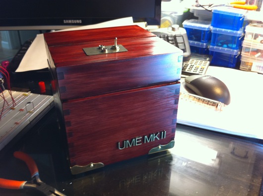
I finally finished my own UME Mark II for my own desk for me! Woohoo! My flavor of useless machines ever has a "presidential" look, as some have put it.

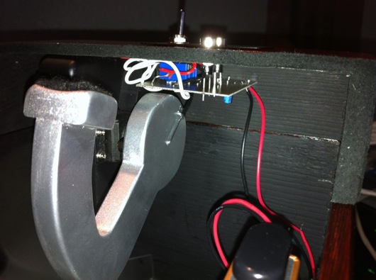
This latest model is the first version of the UME Mk II that incorporates a small PCB (printed circuit board) underneath the lid that is attached directly to the pins of the On/Off switch and the two LEDs. It has all the discrete components required to drive the modified servo. It saves time in soldering and it tidies up the wiring under the hood of this magnificent machine.
The wiring that is there comes from the servo, the "parking" switch, and the battery. The next machine I make will have slightly better placement of the board relative to the arm. The clearance was a little tight for my taste, but it still turned out great. This first version of the integrated PCB required some hand-tweaking. I had to cut a couple traces, solder a couple of jumper wires, and notch a little corner out of the board to allow clearance for the parking switch.
The parking switch is the little microswitch inside the box that the arm trips when it retracts back into the box. Its purpose is to cut power on the back swing of the arm. When you flip the On/Off switch to On on the top of the machine, you give power to the circuit and the arm releases the parking switch. When the arm moves the On/Off switch to Off, it actually reverses its own direction. It then heads back into the box until it presses the parking switch, which cuts off power again.
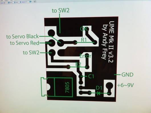
The "3.2" version number is truthful: I revised that silly drawing about 3.2 times. The one above is the latest that incorporates the cuts in the traces I had to make on my machine's PCB. It also takes into account the trimming I did in one corner of the board. In the diagram, I just trimmed the entire edge so that it was still rectangular and easier to cut out.
Everywhere you see black is where there would be copper left on the PCB when etching is completed. The green lines and labels are there for reference but are not printed on the final PCB. The white lettering in the black gets etched out of the copper on the PCB. The little circles at the ends of the traces and a few other places in the black areas are drilled with little bits under my drill press. The final PCB turns out nicely, for a home-brew board, I think.


