It's no secret that if you read at least two articles on this blog you know that I know just slightly more than diddly-poo about electronics. That's OK, though! I'm learning and it's WAY fun! It's like making cool stuff with Legos™ but with the caveat that you could electrocute yourself or start a fire. The other day, I tore down an RCA radio and CD alarm clock that my wife had owned for a while. Its LCD display was failing. We didn't really have a used for it, so I took it apart. I got a great collection of little tactile buttons and motors and other cool circuit boards full of capacitors and diodes and whatnot. But, two of the coolest parts I got were a couple of pretty beefy but small 8-ohm speakers with really great range. They sound awesome when hooked up to something that can drive them properly.
I decided to build a quick amplifier circuit around the LM386 amplifier IC. It's an 8-pin DIP and it is really easy to get going if you're past the super-newbie stage. Or, at least if you are me. I fried two of these in the very early stages of my electronics experimentations. That's an accomplishment, since the versions I have of this IC can withstand up to 15VDC or 18VDC (I can't remember what the National Semi datasheet said). I was young and stupid and needed the lesson.
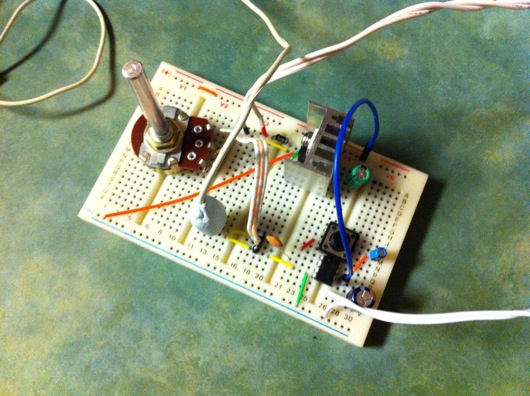
Here is the breadboard of the circuit...
The potentiometer is the volume control. The heatsink is screwed to an LM7812 12V voltage regulator. There are a couple of caps and a diode on there. The wire with what looks like gum on the end of it is actually the headphones jack wire with a three-pin header molded onto the end using that really cool putty "as seen on TV" that you knead together and it forms really hard parts. I used it to protect the super-thin wires of the headphones jack. The little chip on that board is the LM386. The red- and black-tipped wires coming into the top of the breadboard just left of the diode and the voltage regulator are the leads from a Radio Shack 12V, 500 mA wall wart.
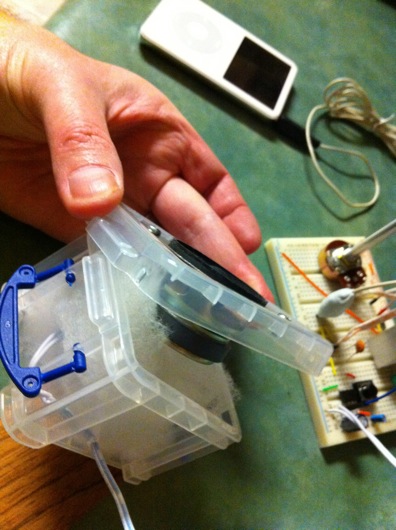
I salvaged some really impressive little powerful speakers from an RCA clock radio and then made a quick little cabinet for one of them in a plastic parts container I had on my workbench. I used the batting that was behind the speakers in the radio, as well:
It was sufficient enough to make the speaker sound much better while testing. Of course, if I build a proper iPod speaker set, I'll do a better little fun cabinet for each speaker AND I'll proper match the iPod's kinda-non-standard line-out voltages.
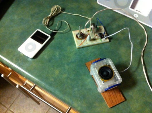
Here is the entire 12V circuit connected to an iPod:
When I pressed the little plastic speaker box against the kitchen counter more tightly, the bass was impressive. So, it seems a well thought-out speaker cabinet for these speakers could potentially make a really nice portable little speaker system. I can't remember what the wattage listed on the back of the speakers was, but it wasn't shabby. I have a number of sets of really nice small speakers I've purchased over the past couple of years for future speaker projects. They've all got pretty decent response. These little guys were lucky finds in a salvage project, so yay!
As I wirte this, I am not at my MacBook on my electronics bench, so the exact circuit diagram escapes me. Here is one that I think is VERY similar and would probably work well:


