Starting the next generation Fitbit Cheat-O-Matic, but changing the name, switching to proper high-end bearings, and make a sturdier base and cam follower mechanism. Should be slick if everything fits nicely and plays nicely.
It's been a little while since I posted an update on the latest version of the Office Chairiot motorized office chair (the, "Mark II"). I usually add little pieces of updates to the project site for it on Local Motors' personal project website, since I plan on utilizing their facilities to push it to 11.
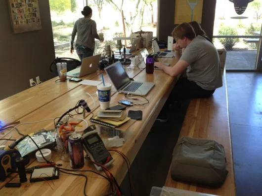
Every few months I organize a hack day at the office, usually on a Saturday. This past Saturday we had our 5th installment of hack/make/tinker day at meltmedia and the turnout was great! Attendance was 8, up from 3 the last time around. YESSS!
I believe I've mentioned it before: I work at an amazing web and software development shop called, "meltmedia." We have a gaggle of highly talented software engineers, web developers and designers. Sometime back in 2011, meltmedia was in search of a new tag line to kick off a for-real live marketing campaign. Marketing was something melt hadn't worried about before then.
While in San Francisco at the 2011 Apple World Wide Developer Conference, in a bourbon-fueled barrage of submissions to the company's on-line suggestion box for new company tag lines, I came up with, "We are Interactive Superheroes." It stuck and I won a $90 bottle of bourbon. Woohoo! To be clear, I am fueled by many things: Caffeine, sugar, soda, etc., not just bourbon. I like chocolate milk. I happen to be a major bourbon geek and had been sampling fine bourbons at a speakeasy in San Francisco called, "Bourbon & Branch" before I went back to the hotel and started submitting dozens of mostly silly ideas for meltmedia's new tag line.
For the short attention span version of this, here is a photo of the three partners of meltmedia in their full costumes with their props:
We'll start with the biggest prop: Mike's Techno HAMMER (Highly Active Mike Moulton Energy Repeater). I needed this thing to be big. I didn't have much time for any of these props, especially the HAMMER. To sturdy up the thing and to keep it as lightweight as possible, I started with green foam from Michael's:
The handle is a piece of PVC pipe from my pool equipment upgrade last year. I knew I'd eventually find a use for the pipe!
At first, I wasn't going to get all electronicky on this thing, but it just didn't seem right to have a TECHNO HAMMER without random blinking LEDs on recycled circuit boards, so, this thing needed a circuit to make random LEDs blink. It also needed a way for Mike to turn on and off the LEDs at will. I did this by embedding a standard pushbutton in the handle:
I cut a hole for the button, then cut a BIG hole behind it to allow me access for glueing. To be sure the button would be at least somewhat difficult to push through the handle, I jammed a piece of leftover green foam into the handle and behind the button before I closed up the back of the handle:
To crappily simulate leather wrapping on the handle, you can see in the image above that I took strips of Gorilla® tape and folded one edge, then wrapped up the handle at an angle. It kinda did the trick. Ya do what ya can in the time ya have, ya know?
The button was in between the batteries and the LED blinking circuit. A simple momentary power-on functionality. The circuit was an Atmel® ATmega328 AVR® microcontroller (same one used in certain models of the Arduino). It was programmed to strobe the LEDs (rifle through each of them and turn them on or off many times per second, like a TV scanline). To keep the current draw to a minimum (to prevent the AVR from cooking), I had all of the LEDs cathodes return to ground through a dinky little constant current devices (CCD) from ON Semiconductor (part number NSI45020T1G). There are 12 LEDs. 12 pins on the AVR are randomly set to be on during their time slice or off. The little CCD kept the current to 20 mA for each LED. This allowed me to use red, green, yellow, and orange LEDs, regardless of their required forward voltage, since the current was always 20 mA, which they all liked. The other reason for doing it this way instead of a resistor was power consumption: The CCD is way more efficient that a resistor that dissipates heat to get the current to where it should be. The circuit was powered by two little AAA cells, so the voltage was about 3 volts DC. Since the microcontroller drew very little power and the LEDs were only on one-at-a-time, the batteries should last for days and days if left on continuously. I did run a test and they stayed lit for about 4 days before I had to assemble the HAMMER circuit. Here's the circuit and batteries:
And here is the ugly underbelly of the circuit (again, time was not on my side, therefore beauty was not on the HAMMER's side):
The next part of the LED circuit is the 12 LEDs that poked through the recycled circuit boards (I'll get to the boards shortly). I drilled holes in old boards pulled from an old (and quite large) oscilloscope that was given to me but that did not function. Each LED was given its own wires and a nice heat-shrink tubing treatment:
Two fairly similar old circuit boards were used for the two sides of the HAMMER. I drilled appropriately sized holes in kinda-random places and poked the LEDs through and grouped the wires together, connecting the grounds together:
Each side's wire bundle would go through little holes in the foam core of the HAMMER and into a secret compartment that held the circuit main board and the batteries:
The compartment was crudely cut (like most of this sad but fun project) into the foam core:
The LEDs looked right at home in the old PCBs:
The shell of the HAMMER was just cardboard faces stuck together hideously and hurriedly with Gorilla® tape. The cardboard was coerced into shape around the foam core:
The entire thing was eventually covered in Gorilla® tape:
Next came the primer and silver metallicish paint for the shell. Turns out, Gorilla® tape doesn't take primer as well as I had hoped. But, it was good enough for the intended limited use:
In the image above, you can see the circuit/battery compartment door and the makeshifty little riveted Velcro® closer... Thing:
Yes, it's cheesy and not at all indicative of a quality or sturdy product, but, again it serves its purpose well enough. Here's what all the crap looked like crammed into the compartment:
Finally, I soldered all 14 of the LED leads to the circuit board and connected the batteries and pushbutton and it was ready to go!
The photo doesn't show it randomly lighting LEDs, of course, so here's a video of the LEDs in action:
And finally, here is Mike actually being an Interactive Superhero with his Techno HAMMER:
Well, we've moved into a new and larger space at the office and we sit at these massive wood and steel desks as teams. Our team decided we needed more "flare" at our desk, so, of course, a big-ass warp core was the first thing that popped into our heads. How hard could that be?
The rings of the warp core will be clear-ish fiberglass. The original master, over which we'll make a fiberglass mold for all eight rings, is made of a giant laminated wood block we need to turn on a big lathe.
Turns out, I was wrong about Elmer's Wood Glue: It most certainly does stick heartily to plastic tables. My wife wasn't too thrilled about the weird globs of dried glue on the table, right before a big pool party, so I spent a solid half-hour with a wood chisel scraping off those nasty little glue-scabs. Ick and neat at the same time.
Aside from the general shared engineering tasks, I am in charge of lighting this bad bay. I looked into electroluminescent strips, but it's too expensive and, frankly, not bright enough for our tastes. So, LEDs will be the lighting source of choice on this one. As you can see from the photo above, these inexpensive little 5mm LEDs are plenty bright enough.
The only complaint I have is that they're very directional. At first I thought that I'd just sand them to diffuse the light. But, after some tinkering, I'm going with a sneaky little angled approach: Point the LEDs in a ring at an angle out from the center of the ring so that its light hits the backside of the fiberglass ring in a sorta elongated oval thing. The light from each of the 30 LEDs in a ring will then overlap and make a nice-looking light ring from inside each warp core ring. But, here is my test rig for the LEDs:
The idea with the LED monster above was to see which worked better for diffusing the LED beams better: Point the LED straight out (left LED), or bend it back toward the reflective foil (right LED) which is convex and should spread the light better. Of course, light dies off over distance and the more we bounce it around, the less of an impact it makes. Below is what the LEDs are projecting without blinding the iPhone camera:
So, looking at that photo, you see the reflected LED gets a little black spot on the sun today (Sting) in its beam. The other is brighter, but more concentrated. So, we'll see how my idea of pointing the LEDs at the inside of the fiberglass rings at an angle to lengthen the shape of their beams.
I started out by building the microcontroller and MOSFET circuit, complete with firmware that pulses and fades the LEDs. The speed that the rings pulsate into the middle is set by a potentiometer, at the moment. I think I may add the ability for it to try to pulse to the beat of music. Who knows?
Here is the circuit for the LEDs in action:
The microcontroller is my old favorite, the Atmel AVR. This one is an ATmega328P in the PDIP package. The rings of LEDs (in this video, the lines of LEDs) are powered by 12 volts DC and are controlled by N-channel MOSFETs. Each ring will have a total of 30 LEDs. Each ring will have 10 groups of 3 LEDs plus one resistor all run in parallel on the 12-volt rail. Pretty standard stuff.
Because of the size of the middle section, the matter-antimatter combustion chamber is quite large in our model, we decided to try making a big round thing of foam and then carving that down to the outside shape of the chamber. We'll then (theoretically) cover it in fiberglass and refine the resulting shell after that.
That's it for this update. I'll get more up here as we progress. Thanks as always for following my blog!


 to be carved for matter-antimatter combustion chamber")