
I have always engineered (I'm using that term loosely) my projects by the seat of my pants. I will get an idea and I just start plugging things together. At best, I will breadboard parts of a larger electronics project to make sure the ideas work, but mostly, I just build on-the-fly. Grab a piece of wood and throw it on the bandsaw, try the fit, trim it there, sand it there and then glue and screw. Quick and easy. Just me, the material and the tools.
That changed with the start of the design process for Office Chairiot Mark III (3rd generation, to be clear) project. Now that it's getting closer to a possible product (or maybe a collection of smaller products and kits), there will be more collaboration required. That means I'll need a more well-defined plan that others can act on. That means CAD: I need plans with dimensions and instructions. And, as it it turning out, I should have been using this amazing tool all along. I now consider CAD one of my most important maker tools.
One of the first CAD-designed things I put onto the Office Chairiot Mark II, a direct result of a CAD file, was the crazy aluminum control panel enclosure. Its outline (the face and placement of the controls) and general dimensions were put together in Adobe Illustrator and exported as DXF files so that the fabricators could turn that into something useful for their water jet people and the actual fabricators who were going to build the enclosure.
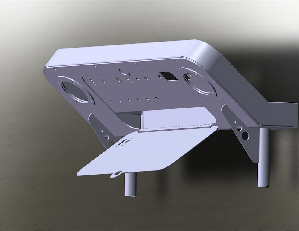
2nd version of the Office Chairiot Mark II control panel enclosure in Solid Works
I also actually did CAD up parts of the chassis on the Office Chairiot Mark II because we had to cut the aluminum parts with the water jet at Local Motors. It was the first time I'd taken a CAD drawing (from ViaCAD 9 Pro on my Mac) and had gotten an actual real thing out of it without the help of a paid fabricator.

Solid Edge design of the Office Chairiot Mark II aluminum chassis on the plywood frame
Other than than for visualizing my brick pavers and fire pit, I've not generally taken the time to properly design and fit my projects together virtually before building them.

Rendering of Backyard Fire Pit and Pavers in Blender 3D
OK, I guess I've done quite a bit of CAD work for past projects. Point is, I haven't used it enough. It's pretty darn cool to see a virtual version of something before spending time actually building it. It does add overhead in time, but knowing ahead of time how things will fit together makes the build go faster. Of course, professional engineers and designers who read this will say, "Um, duh?" :p
So what CAD program do I use right now? I am currently using Onshape and I love it. It's in beta and you can get an invite to it. New features are being added rapidly. The docs and tutorials are excellent already. The interface is clean and easy to use. Jon Hirschtick, the former CEO of SolidWorks, and a team of very talented CAD system engineers have built what I think is going to be a huge player in the new maker and industrial design game. CAD in the cloud will be the norm, I think. I've already witnessed first hand how amazing and convenient it is to be able to get to my work anywhere.
Here are some excellent articles on this very topic, if you'd like to take a side trip from this article:
Onshape in the Chrome browser on a MacBook Pro laptop
Onshape, like any good and professional-grade CAD application, uses parametric modeling. You define the model using dimensions and formulae. Things start out nice and precise. You piece together the parts. Pieces of your overall design build on other pieces of the design. Change one dimension, and if you've set up the original sketch of that part correctly, everything related to that part will update for you. It's no longer scary to make changes, big or small, to your designs. Very easy. Very un-scary. Very cool. Super efficient when it comes to making changes.
I have Autodesk Fusion 360 and ViaCAD 9 Pro (very cool native Mac CAD app) installed on my Mac Pro at home, but as of the writing of this, I've settled onto Onshape. I was really getting into Fusion, but when I discovered Onshape at Local Motors, it was an easy choice. One big reason in choosing Onshape is that I am collaborating with Local Motors on the Office Chairiot project. Onshape allows for easy collaboration AND it does version control. Being a software developer, I can appreciate good versioning for files of any kind.
Onshape running on my iPad
Onshape on my iPhone
Another thing Onshape does very well, which I've already taken advantage of, is that it runs on my iPad and my iPhone. While an iPhone screen is the most ideal way to do CAD, it does work and it works well. On the iPad, it's very easy to work with, even with the touch interface. I used it extensively while waiting in the customer lounge at the dealership, waiting for work to be done on my truck. I regularly show people the work to date on my iPhone, spinning the models around just like I would on my desktop.
The first start-to-finish project I've done with it (officially) is my 4x8 sheet holder in the garage.
4'x8' panel holder for garage
It's 6 pieces cut from about a 4'x4' piece of 3/4" MDF. I designed it first in Onshape.
4'x8' panel holder design in Onshape cloud-based CAD
I was able to figure out how much angle and depth I needed on the vertical brackets in order to keep the top edges of the panels from resting against the garage wall. I don't think I would have gotten that right by just cutting pieces to fit together on-the-fly. :)
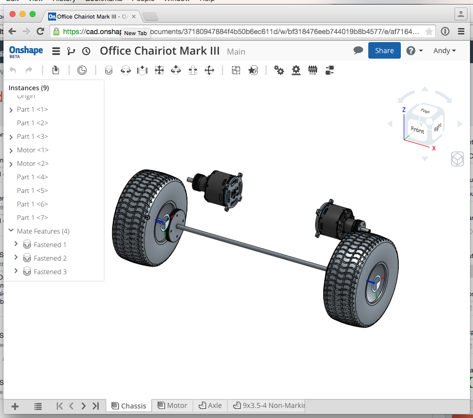
For the Office Chairiot Mark III, which is the project I used to really learn Onshape and parametric modeling in earnest, I started modeling the Turnigy outrunner motors that will eventually drive the latest Office Chairiot via grooved belts.
The real brushless motor and the CAD version
I sat there with the motor and my digital calipers and measured and drew. It's an accurate enough representation that I should be able to output the profiles of the back plate and pulley bolt patterns to water jet cut the brackets and to CNC the custom pulleys.
Since I am building the Office Chairiot Mark III around the motors, wheels and batteries, I next modeled the tires in Onshape.
Non-marking 9.5" scooter tire modeled in Onshape
I hadn't received the tires at the time I modeled them in Onshape. I used the specifications and photos on the website from whence I purchased them and modeled what I think is a pretty darn accurate rendition of the real thing. I verified everything once I received the tires. Worked great, right down to the tread!
Once you get the hang of how to add and subtract material from objects, designing this way is super-easy. I love it. If you want to check it our for yourself, go to http://Onshape.com and request a beta invite. I highly recommend it.