Fitbit Cheat-O-Matic 2: 3D Printed Mechanical Simplicity
I’ve been getting more into 3D printing, lately. One of the many things I felt could benefit from 3D printing technology was the Fitbit Cheat-O-Matic (version 1) I wrote about a while ago. It’s very funny (as in, I built it as a joke; see previous linked article) and it even got some press at BBC.com. The crazy thing is I’ve gotten a number of emails from visitors to my site asking if I could build them one. They all were willing to pay for it, as well. That’s cool. I don’t judge. 😉
The first design was kinda simple and never really built to run indefinitely; on the contrary, it was meant to last long enough for the office Fitbit competition at the time (about a week I think). It was enough to get me through a competition, anyway. Certainly not a design I’d wish to build multiples of and then sell. They would have all failed soon after their users started them up. Turns out RC servos, even the high-quality all-metal-gear ones. I killed three different kinds of servos, one of them being VERY expensive.
I was watching old engineering videos from 1939 on YouTube one day and saw a cool demonstration of a cam and follower in a machine of unknown purpose. I realized then that I could make a very simple contraption using 3D printing and a geared DC motor to shake a Fitbit up and down very easily. It could be super-simple to assemble, cheap to print all the parts but the motor and probably run off a simple 12V wall wart power supply.
This is the CAD design of the new Fitbit Cheat-O-Matic, done in Onshape cloud-based CAD:
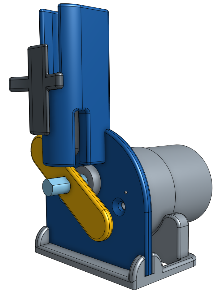
Fitbit Cheat-O-Matic 2 3D CAD Rendering in Onshape
The yellow piece is the cam. The dark grey piece with the cross thing on it is the follower and also the holder for the Fitbit. The light blue shaft sticking through the cam is the shaft from the geared down part of the 12V DC motor. The big round cylinder in the back is the motor. The lighter gray and dark blue stuff is the base. The dark blue piece is the part of the base the gear motor is attached to using two screws. The base fits onto the bottom of the faceplate with a simple tab and the two sets of side supports. Here is the exploded view of the CAD rendering:
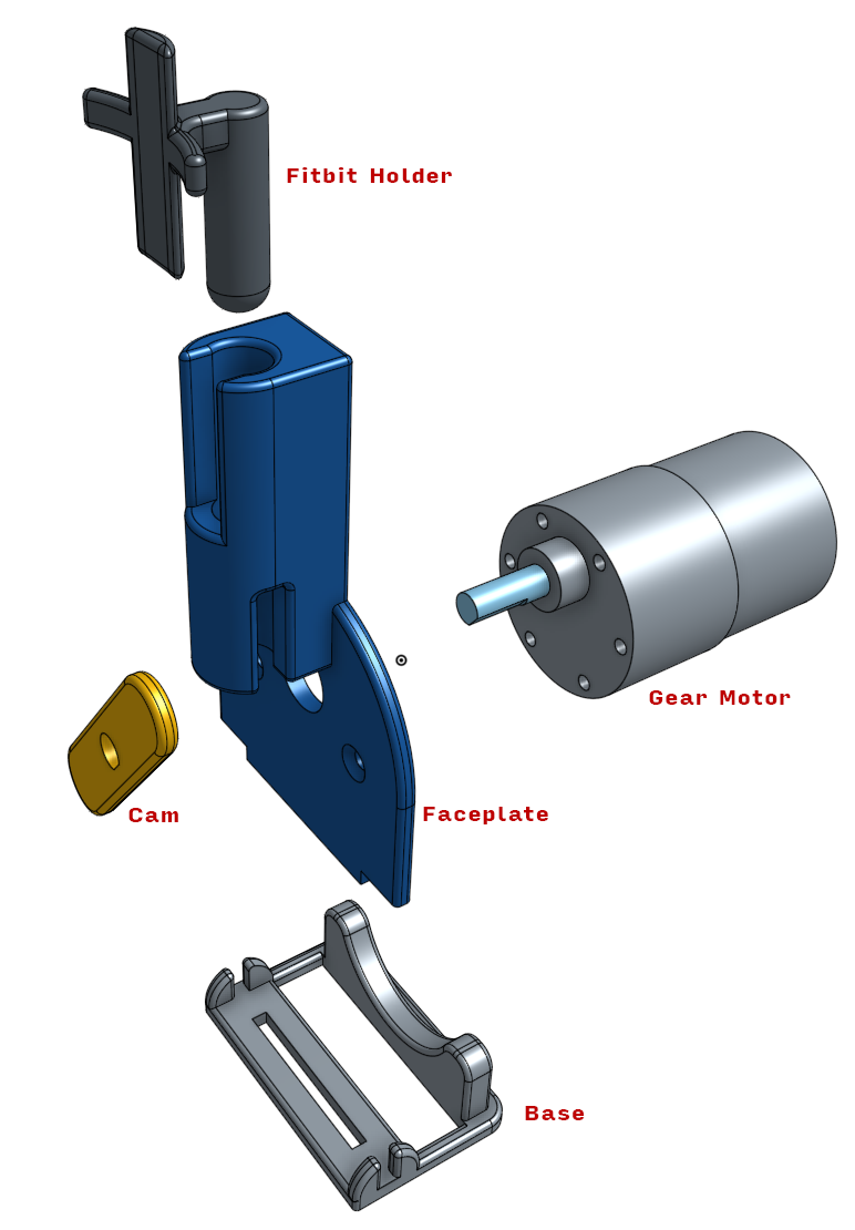
Exploded view of Fitbit Cheat-O-Matic 2
I 3D printed the parts at Xometry (http://xometry.com). The tolerances on this first attempt were a little tight, so I’m changing up the CAD a bit to save me some plastic shaving and trimming. That’s mostly because I’m still kinda new to 3D printing. The total cost for the four parts and shipping was about $50. If I got around to buying a 3D printer, that would be much cheaper, of course.
The 12V DC gear motor came from Robot Shop (http://www.robotshop.com) and cost about $25 with shipping. The gear motor is design to run at about 58 RPM. Since the cam has two high sides, it pops the Fitbit up and down about twice a second which is a pretty brisk walk, if not a run.
The screws I already had on hand. The power comes from a cheap 12V wall wart power adapter from Radio Shack. Anything that can provide about 60 mA of power will suffice. That’s the draw I measured while it was running with a Fitbit attached. 1 amp adapters are pretty easy to find.
Here’s the Fitbit Cheat-O-Matic 2 in action:
Originally, I’d designed a gap between the cam and the holder for a 1/8″ steel ball, thinking that would allow smoother operation. Turns out that caused a tiny bit of binding which made the device louder and made the motor work harder. Without the bearing, the plastic-on-plastic is quite smooth and doesn’t appear to be wearing at all.
As far as efficiency, as I write this it is 8:38 PM. The Fitbit app says the machine has racked up 116,000 steps since midnight. I think it’s on its way to about 135,000 for a 24-hour period. I was told there’d be no math.

Screenshot from iPhone for Cheat-O-Matic stats for today
I will compete separately from the Fitbit Cheat-O-Matic 2 in future office competitions. I’m a healthy person with a healthy sense of humor, so don’t go off on a “that guy’s lazy” rant. I am lazy in that I prefer to find faster ways to do things, but I’m certainly not a slug or a lump. Let’s keep that straight. 😉
I like making things even if they have no real useful purpose. THIS device certainly qualifies. If you’re interested in purchasing one, drop me a message. I’ll work on getting them up on my store on this site. Haven’t worked out a price since everything has been purchased at one-off pricing.
Be the first to comment