PC Power Supply Repurposed for Bench/Breadboard/Tinker Use
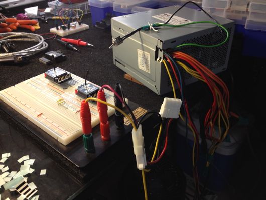
A friend and coworker of mine sent me a text today asking if I had instructions on how I built my benchtop power supply from a computer power supply. I realized that I had not written about that on this blog. That was dumb. Simple oversight. Anyone coulda done it. I've been using that silly thing for a long time and I think it might even be in the background of a couple of videos of photos up here. Funny. Anyhoo... Here's the quick how-to-karate-chop on how to take a PC power supply (ATX) and use it on your electronics bench as a clean source of DC power at 3.3V, 5V and 12V (and even -12V, actually). Let's start with a picture because I have a short attention span if there aren't visuals:
A word of caution: It's electric. Don't be stupid. The Dell power supply pictured above us hooked up to mains power and can supply your circuits with upwards of 14A at 3.3V, so, again, don't be stupid. One cool feature of this Dell (and I'm sure of many ATX supplies) is that it will instantly shut down when you short things out. That might be advice from experience. No sure.
When snipping wires and protecting the ends and whatnot, BE SURE THE POWER SUPPLY IS DISCONNECTED FROM THE WALL OUTLET! As with any of the silly things I build, if you imitate me, you do it at your own risk and I warranty NOTHING on this site, from instructions to ideas to schematics to whatever. Nothing. I've worked around the guts of PC's since the IBM XT days and I'm here to talk about it, so it must not be that scary.
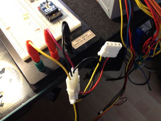
Throughout this article, as with most of my articles, please forgive me for not knowing the nomenclature of connectors and parts. That said, I rigged up a 4-pin Molex connector with banana kinda connectors that slip into the tops of the power connectors on a standard breadboard. This makes it really easy to connect 3.3V, 5V or 12V to my breadboards.
Usually, I wait to worry about the "how" of a power supply for a circuit until I get the core of the circuit working, so a quick supply of the standard voltages is nice. Plus, with an ATX power supply, I can get upwards of 10 amps or so. For instance, I've been working on a circuit that controls a sealed environment's temperature using a thermoelectric cooling device ("TEC") and at upwards of 15VDC, it will want to draw about 3A. My benchtop digital power supply can barely make that. The ATX supply, on the other had, does it handily.
Why did I choose a PC power supply and not just keep using my digital benchtop one (aside from the amp draw on one of my experiments)? I found that I was almost always setting the supply to 3.3V, 5V or 12V. Crazy how the PC supply does all three of those.
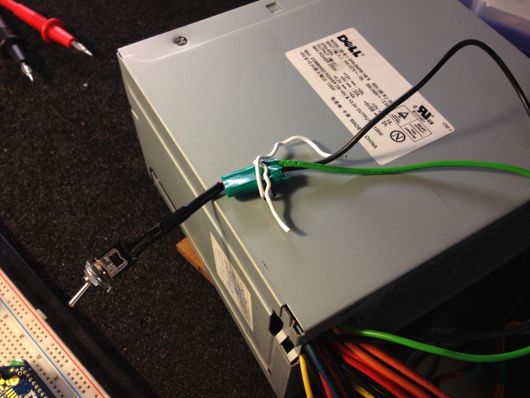
To turn on and turn off the power supply easily, I connected a switch between the ATX 20-pin main board connector's pin 14 ("PS_ON") and one of the ground wires:
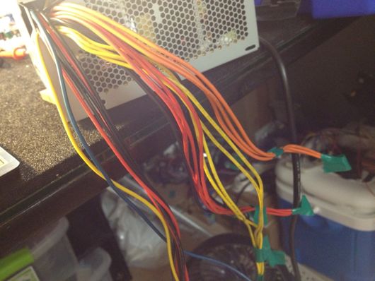
Any other wires from the 20-pin connector were cut back,taped off and tucked inside the power supply's enclosure for safe keeping. I kept all of the many 3.3V (orange), 5V (red) and 12V (yellow) wires full-length and ready to be connected to my future screw terminal block that will sit conveniently on my bench for quick hookups.
The dark blue wire is -12VDC and is handy to have for amps and stuff, so keeping that one handy, as well.
I'll add more to this post once I get the screw terminals finished.


